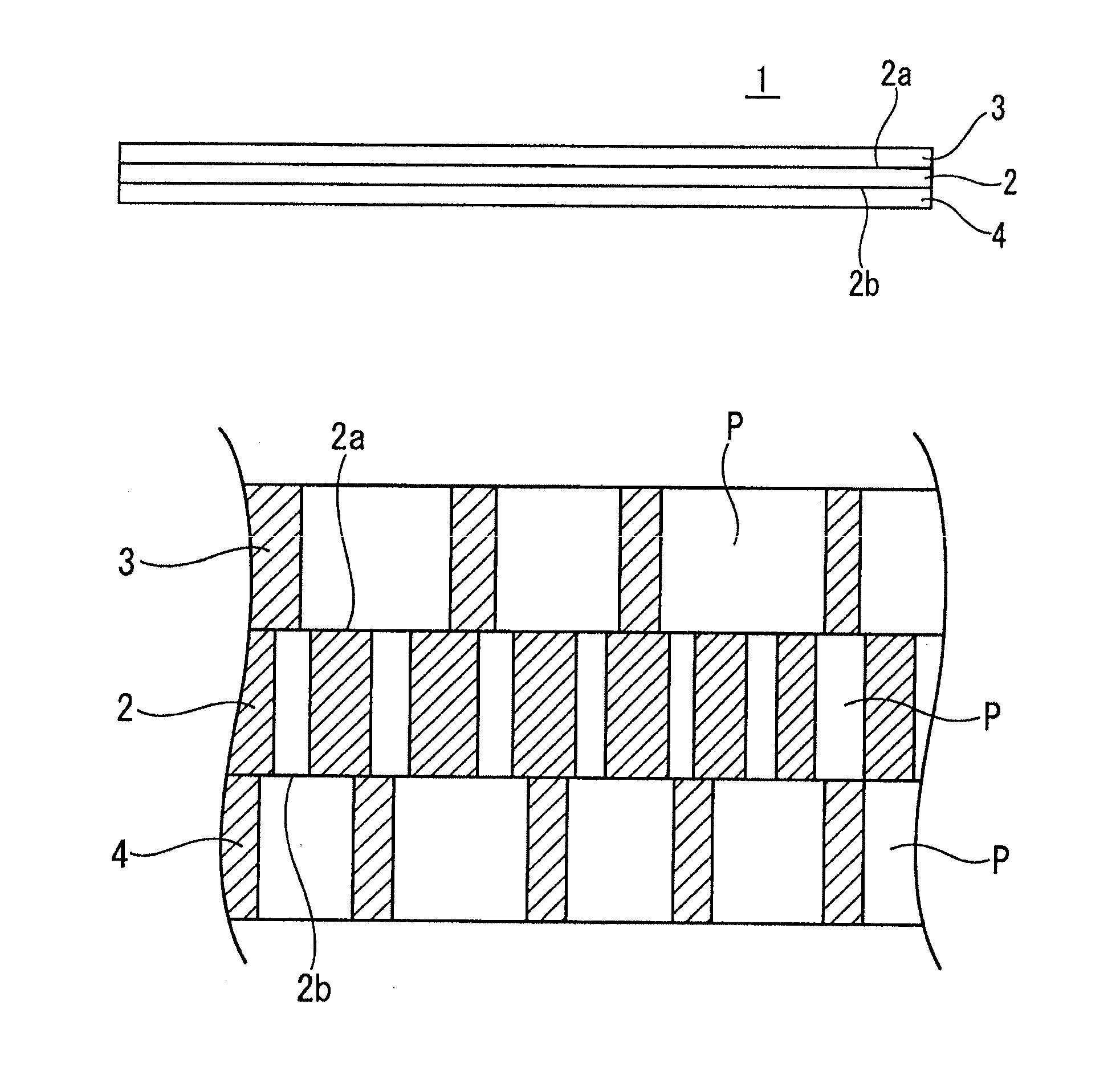
Porous multi-layer filter
a multi-layer filter and porous technology, applied in the direction of filtration separation, membranes, separation processes, etc., can solve the problems of affecting the yield of products, affecting the performance of products, and reducing the pore size so as to prevent a decrease in the filtration performance, improve the strength of the filtration layer, and improve the permeability of the liquid to be treated
- Summary
- Abstract
- Description
- Claims
- Application Information
AI Technical Summary
Benefits of technology
Problems solved by technology
Method used
Image

Examples
example 1
[0111]18 Parts by mass of a liquid lubricant (Supersol FP-25 manufactured by Idemitsu Petroleum Co., Ltd. (constituent: naphtha)) was added and mixed to 100 parts by mass of PTFE fine powder (PTFE 601A manufactured by DuPont). The resulting mixture was subjected to compression molding in a molding machine to form a block-like shaped body.
[0112]Next, the block-like shaped body was continuously extruded into a sheet-like shape. The sheet-like shaped body was passed through calender rollers, further passed through heating rollers (130° C. to 220° C.) in order to remove the liquid lubricant, and wound up on a roll to obtain a sheet of 300 μm to be used as a sheet for forming a filtration layer. Furthermore, a sheet of 250 μm was obtained as a sheet for forming a support layer and a protection layer.
[0113]Next, with respect to a sheet for forming the filtration layer, after stretching at a magnification of 2 times in the longitudinal direction (machine direction) at a roll temperature of...
example 2
[0118]In order to set the mean pore size of pores of a filtration layer 2 to be 0.05 μm, the stretch magnifications in the longitudinal and transverse directions of a sheet for forming the filtration layer were set such that the first longitudinal magnification was 2 times, the second longitudinal magnification was 3 times, and the transverse magnification was 21.5 times, as shown in Table I. Thereafter, the same procedure as that in Example 1 was performed.
example 3
[0119]In order to set the mean pore size of pores of a filtration layer 2 to be 0.10 μm, the stretch magnifications in the longitudinal and transverse directions of a sheet for forming the filtration layer were set such that the first longitudinal magnification was 2 times, the second longitudinal magnification was 3 times, and the transverse magnification was 21.5 times, as shown in Table I. Thereafter, the same procedure as that in Example 1 was performed.
PUM
| Property | Measurement | Unit |
|---|---|---|
| pressure capacity | aaaaa | aaaaa |
| thickness | aaaaa | aaaaa |
| mean pore size | aaaaa | aaaaa |
Abstract
Description
Claims
Application Information
 - R&D
- Intellectual Property
- Life Sciences
- Materials
- Tech Scout
- Unparalleled Data Quality
- Higher Quality Content
- 60% Fewer Hallucinations
Browse by: Latest US Patents, China's latest patents, Technical Efficacy Thesaurus, Application Domain, Technology Topic, Popular Technical Reports.
© 2025 PatSnap. All rights reserved.Legal|Privacy policy|Modern Slavery Act Transparency Statement|Sitemap|About US| Contact US: help@patsnap.com