Bubble generation for aeration and other purposes

a technology of fine bubbles and aeration, which is applied in the direction of mixers, specific water treatment objectives, fuel gas production, etc., can solve the problems of impossible absolute stationary bubbles (with respect to liquids) and achieve the effects of small size, increased collision rate, and low energy consumption

Active Publication Date: 2013-04-18
PERLEMAX LTD
View PDF4 Cites 31 Cited by
  • Summary
  • Abstract
  • Description
  • Claims
  • Application Information

AI Technical Summary

Benefits of technology

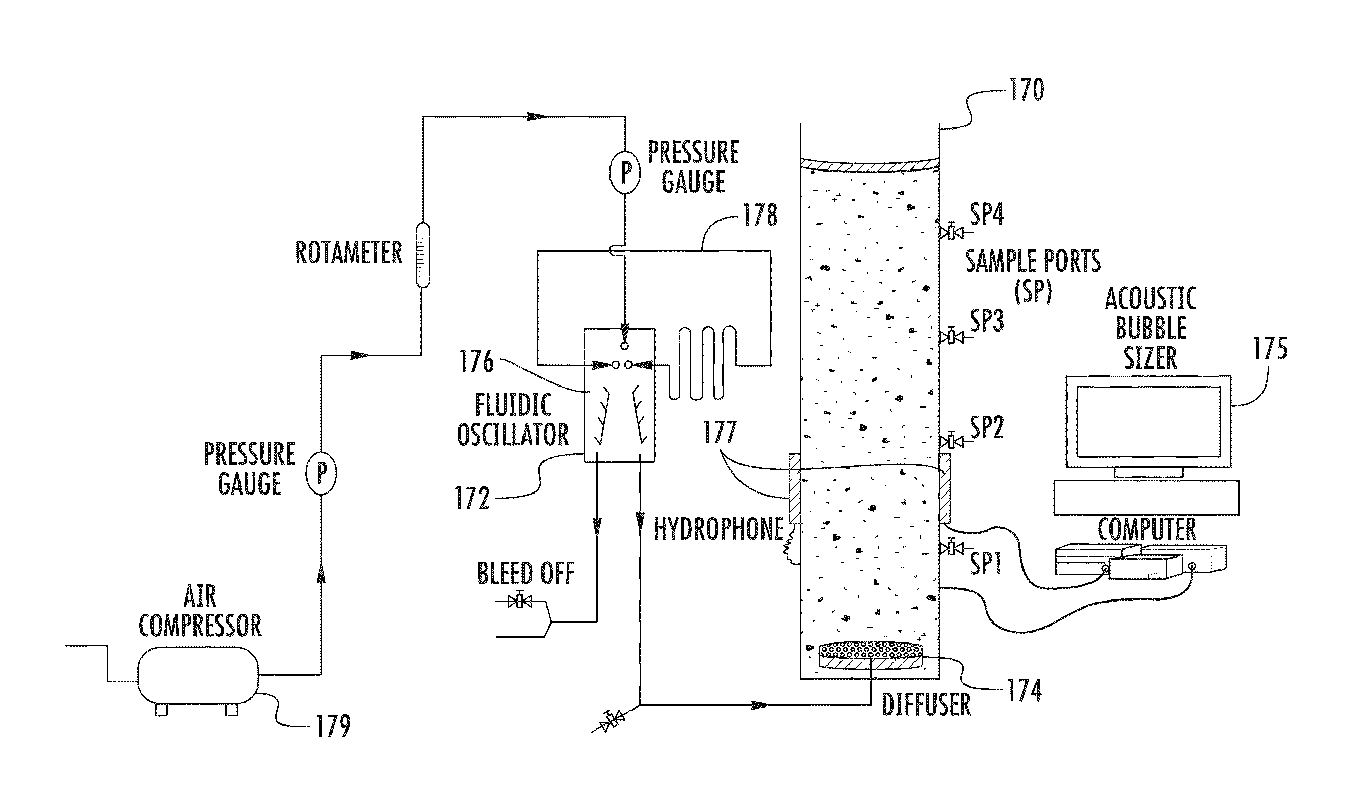
[0088]In connection with the algal separator, as well as in anaerobic and other digesters, such methods of bubble production as described herein are especially beneficial because of their low energy consumption. To introduce bubbles into a tank, the pressure of the gas supply need only be about half a bar higher than the hydrostatic pressure of the liquid at the point of introduction. In a typical tank with a three metre height of liquid, traditional DAF (dissolved air flotation) injects liquid saturated with gas at about 6 bar pressure into the ˜1.3 bar clarifying tank. The turbulence caused by the liquid injection and release of the bubbles, despite their small size, is significant. The bubble production

Problems solved by technology

Absolutely stationary bubbles (with respect to the liquid) are of course impossible because of the density diff

Method used


Image

  • Bubble generation for aeration and other purposes
  • Bubble generation for aeration and other purposes
  • Bubble generation for aeration and other purposes

Examples


Embodiment Construction

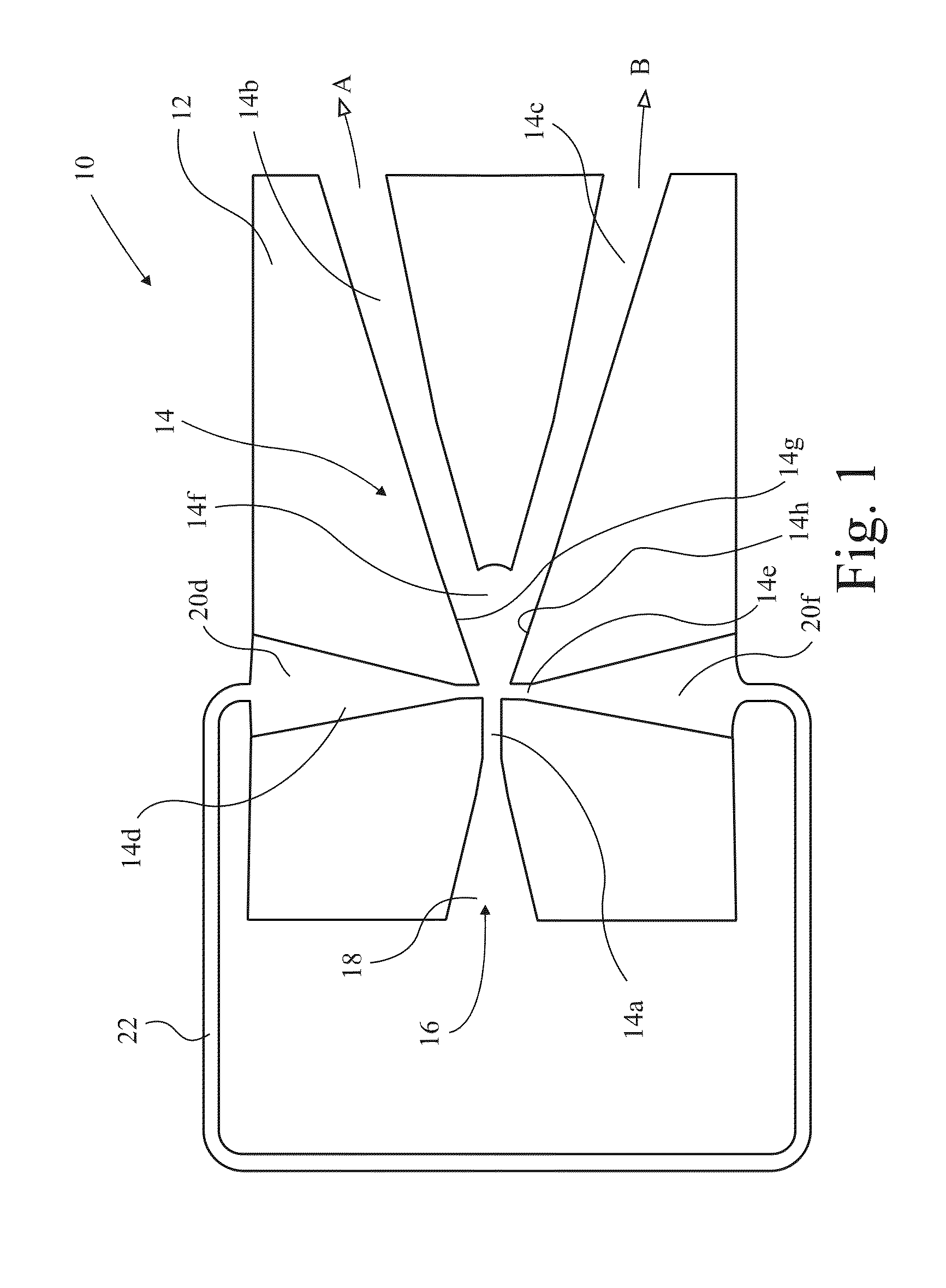
[0119]In FIG. 1 a fluidic diverter 10 is shown in section, comprising a block 12 in which passages indicated generally at 14 are formed. An inlet passage 14a has a supply 16 of fluid under pressure connected thereto by an inlet port 18. Two outlet passages 14b,c branch from the inlet passage 14a. Two control passages 14d,e oppose one another on either side of the inlet passage just in front of the branch 14f between the two outlet passages 14b,c. The control passages are supplied by control ports 20d,f which are interconnected by a closed loop conduit 22. When fluid passes along the inlet passage 14a and enters the diverging branch 14f it tends to cling to one side or the other under the influence of the Coanda effect, and preferentially enters one or other of the outlet passages 14b,c. In fact, the effect is so strong that, provided the pressure region upstream of the outlet passages 14b,c is favourable, more than 90% of flow in the inlet passage 14a will enter one or other of the ...


PUM

PropertyMeasurementUnit
Lengthaaaaaaaaaa
Fractionaaaaaaaaaa
Fractionaaaaaaaaaa

Abstract

Uses of a method of producing small bubbles of gas in a liquid include gas transfer in airlift bioreactors and anaerobic digesters, and particle separation. The method uses a source of the gas under pressure, a conduit opening into a liquid and oscillating the gas passing along the conduit. The oscillation is effected by fluidic oscillator, comprising a diverter that divides the supply into respect outputs, each output being controlled by a control port, wherein the control ports are interconnected by a closed loop. Separation of algae from water involves delivering a laminar flow of microbubbles in the range 10 to 100 μm diameter. Such bubbles also deliver a laminar flow in bioreactors that delivers enhanced liquid flow despite the small bubbles, which improves mixing and also enhances efficiency of gas exchange and retention of the bubbles in the reactor.

Description

CROSS-REFERENCE TO RELATED APPLICATIONS[0001]This application claims priority to and is a continuation-in-part of co-pending U.S. patent application Ser. No. 12 / 447,629, filed Apr. 28, 2009, entitled, “Bubble Generation For Aeration And Other Purposes,” which is a national stage application, filed under 35 U.S.C. §371, of International Application Number PCT / GB2007 / 004101, filed Oct. 29, 2007, entitled, “Bubble Generation For Aeration And Other Purposes,” which claims priority to Great Britain Patent Application No. 0621561.0, filed Oct. 30, 2006, entitled, “Bubble Generation For Aeration And Other Purposes,” all of which are hereby incorporated by reference herein in their entirety.BACKGROUND[0002]This invention relates to the generation of fine bubbles and their application in two processes, one being airlift loop bioreactors and the other being particle, in particular, algal floc, separators.[0003]Bubbles of gas in liquid are frequently required in many different applications and...

Claims


Application Information

Patent Timeline
IPC IPC(8): C02F3/28
CPCC02F3/2866B01F15/024B01F3/04248B01F3/04517B01F3/04978C02F3/1215Y02E50/343C02F3/2873B01F2215/0431B01F2215/0459C02F2301/022C02F2303/26C02F3/223Y02W10/37B03D1/242Y02E50/30Y02W10/10B01F23/23121B01F23/232311B01F23/238B01F35/71755
Inventor ZIMMERMAN, WILLIAM BAUER JAYTESAR, VACLAV
Owner PERLEMAX LTD
Why Eureka
Try Eureka