MOTOR CONTROL DEVICE THAT CONTROLS d-AXIS CURRENT OF PERMANENT MAGNET SYNCHRONOUS MOTOR

a technology of synchronous motor and control device, which is applied in the direction of motor/generator/converter stopper, dynamo-electric converter control, motor/generator/converter stopper, etc., can solve the problems of thermal demagnetization and the inability to generate permanent magnet synchronous motor, so as to reduce the amount of temperature rise

Active Publication Date: 2013-04-18
FANUC LTD
View PDF1 Cites 13 Cited by
  • Summary
  • Abstract
  • Description
  • Claims
  • Application Information

AI Technical Summary

Benefits of technology

[0008]As an aspect, the present invention provides a motor control device capable of avoiding a state where thermal demagnetization of permanent magnets of a permanent magnet synchronous motor occurs due to overheating.
[0015]According to the present invention, the d-axis current command value, in which the amount of rise in the temperature of the permanent magnet in the steady state of the permanent magnet synchronous motor is a minimum, is generated based on the speed of the rotor, and therefore, it is possible to reduce the amount of rise in the temperature of the permanent magnets in the steady state of the permanent magnet synchronous motor to a minimum. Consequently, the loss does not concentrate on the stator or rotor provided with the permanent magnets, and therefore, the permanent magnet is not brought into the overheating state and it is possible to avoid the state where thermal demagnetization of the permanent magnet occurs due to overheating.

Problems solved by technology

When a permanent magnet synchronous motor in which permanent magnets are provided in one of a stator and a rotor is controlled by a motor control device, thermal demagnetization of the permanent magnets occurs due to overheating, and thus there may be a case where it is no longer possible for the permanent magnet synchronous motor to generate a torque in a quick and stable manner.
However, in a conventional motor control device that generates a d-axis current command value, in which the loss of iron and copper is minimum, there may be a case where the permanent magnets enter an overheating state and thermal demagnetization of the permanent magnets occurs when the loss concentrates on the stator or rotor provided with the permanents magnet.

Method used


Image

  • MOTOR CONTROL DEVICE THAT CONTROLS d-AXIS CURRENT OF PERMANENT MAGNET SYNCHRONOUS MOTOR
  • MOTOR CONTROL DEVICE THAT CONTROLS d-AXIS CURRENT OF PERMANENT MAGNET SYNCHRONOUS MOTOR
  • MOTOR CONTROL DEVICE THAT CONTROLS d-AXIS CURRENT OF PERMANENT MAGNET SYNCHRONOUS MOTOR

Examples


Embodiment Construction

[0024]Embodiments of the motor control device according to the present invention are explained with reference to the drawings.

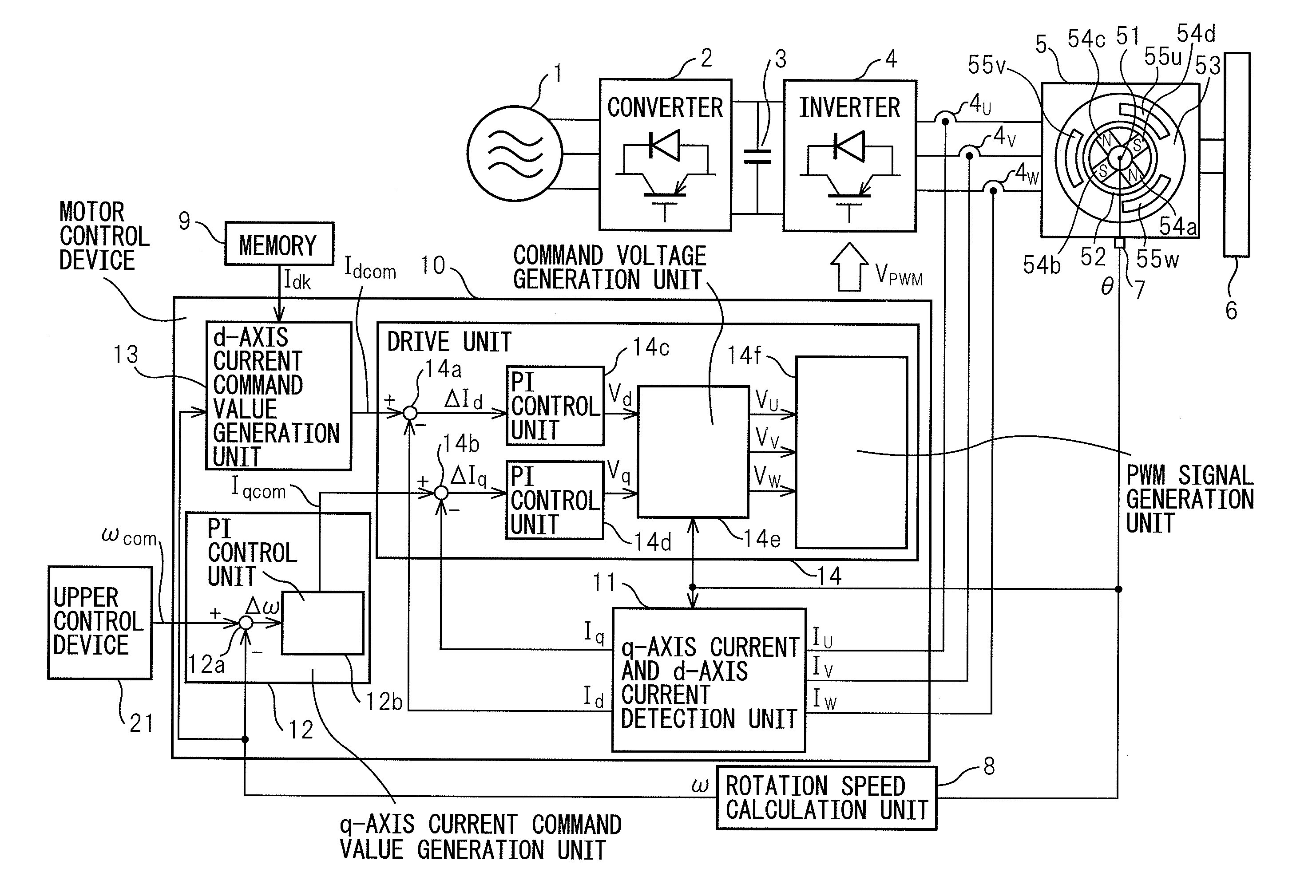
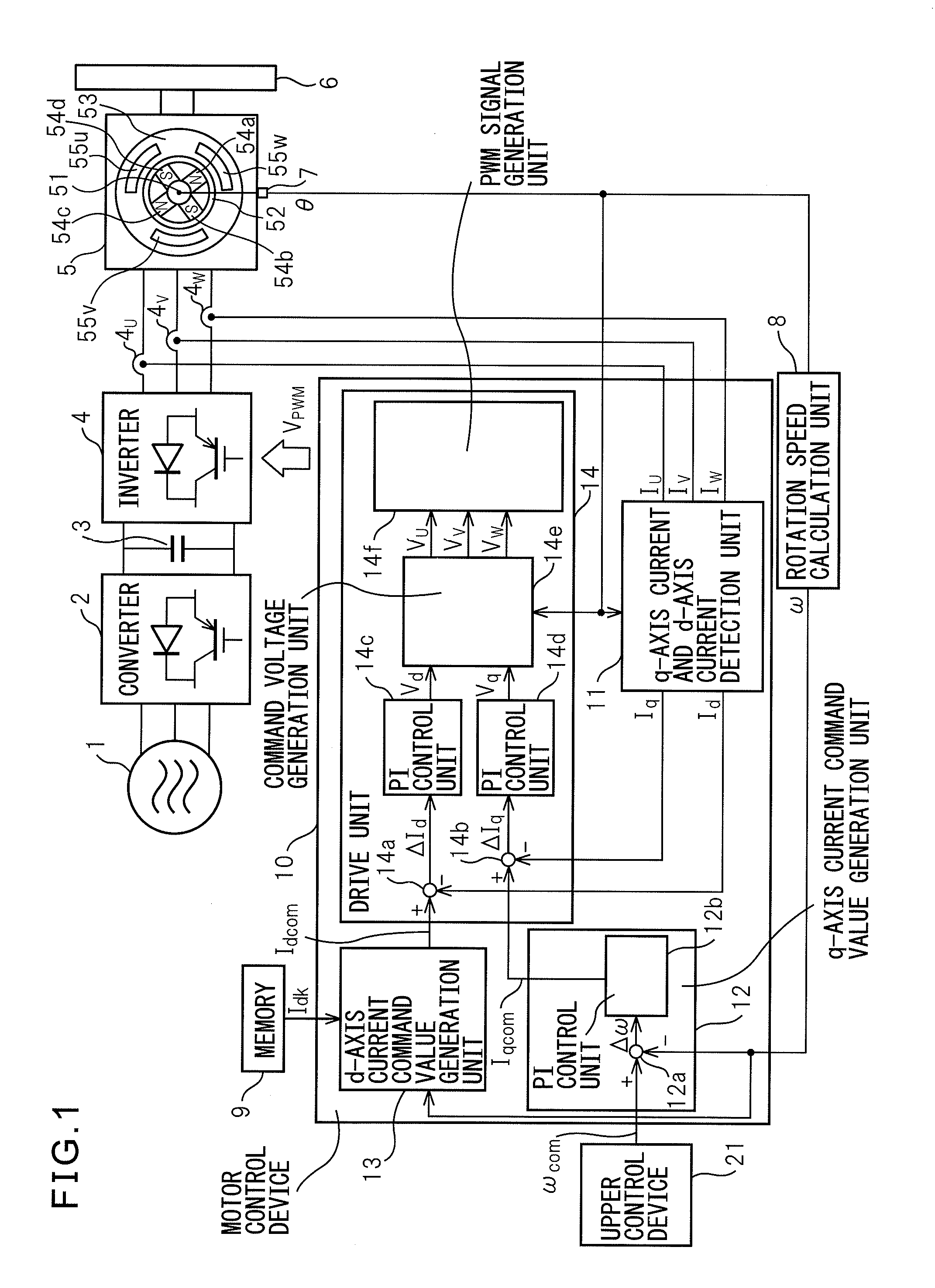
[0025]Referring to the drawings, FIG. 1 is a block diagram of a system having a motor control device of an embodiment of the present invention. The system shown in FIG. 1 has a three-phase AC power source 1, a converter 2, a smoothing capacitor 3, an inverter 4, a permanent magnet synchronous motor 5, a driven object 6, a rotation angle detection unit 7, a rotation speed calculation unit 8, a memory 9, a motor control device 10, and an upper control device 21.

[0026]The converter 2 consists of a plurality (six, in the case of three-phase AC) of rectifier diodes and transistors connected in inverse parallel to the rectifier diodes, respectively, for example, and converts AC power supplied from the three-phase AC power source 1 into DC power. The smoothing capacitor 3 is connected in parallel to the converter 2 in order to smooth a voltage rectified by the recti...


PUM


Abstract

A motor control device that performs vector control to control a q-axis current and a d-axis current of a permanent magnet synchronous motor independent from each other. The motor control device includes a q-axis current and d-axis current detection unit configured to detect a q-axis current and a d-axis current of a permanent magnet synchronous motor, a q-axis current command value generation unit configured to generate a q-axis current command value, a d-axis current command value generation unit configured to generate a d-axis current command value, in which an amount of rise in the temperature of permanent magnets in a steady state of the permanent magnet synchronous motor is a minimum, and a drive unit configured to drive the permanent magnet synchronous motor.

Description

BACKGROUND OF THE INVENTION[0001]1. Field of the Invention[0002]The present invention relates to a motor control device that performs vector control to control a q-axis current and a d-axis current of a permanent magnet synchronous motor independent from each other in order to generate a torque of a permanent magnet synchronous motor having a stator provided with one of a group of windings and a group of permanent magnets and a rotor provided with the other thereof in a quick and stable manner.[0003]2. Description of Related Art[0004]A motor control device that performs vector control controls, for example, a motor in which an AC voltage from a power source (for example, three-phase AC power source) is applied through a converter, a smoothing capacitor and an inverter. In this case, the motor control device detects a q-axis current and a d-axis current of a permanent magnet synchronous motor based on currents (for example, U-phase current, V-phase current, and W-phase current) flowi...

Claims


Application Information

Patent Timeline
Patent Type & Authority Applications(United States)
IPC IPC(8): H02P21/02H02P6/06H02P6/08H02P6/12H02P6/17H02P6/28H02P21/00H02P21/13H02P21/22H02P23/16H02P27/04H02P27/08
CPCH02P6/08H02P21/0089H02P21/0035H02P29/0066H02P21/22H02P29/662
Inventor AKASAKO, YOUICHI
Owner FANUC LTD
Why Eureka
Try Eureka