Diffuse reflective optical films with spatially selective birefringence reduction

a technology of optical films and selective birefringence, applied in the field of optical films, can solve problems such as significant reflection, and achieve the effects of reducing birefringence, selective birefringence reduction, and reducing or eliminating preexisting optical birefringen

Active Publication Date: 2013-04-18
3M INNOVATIVE PROPERTIES CO
View PDF7 Cites 24 Cited by
  • Summary
  • Abstract
  • Description
  • Claims
  • Application Information

AI Technical Summary

Benefits of technology

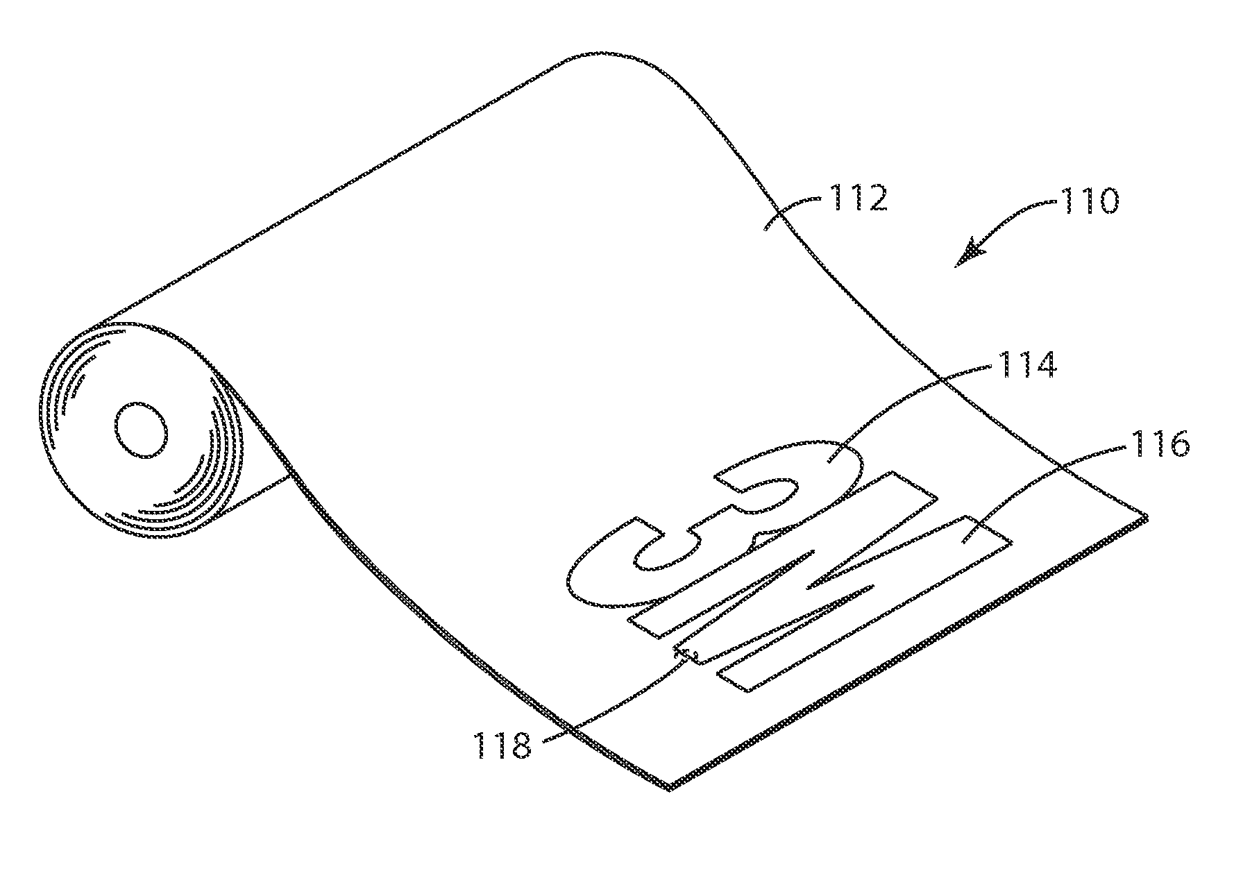
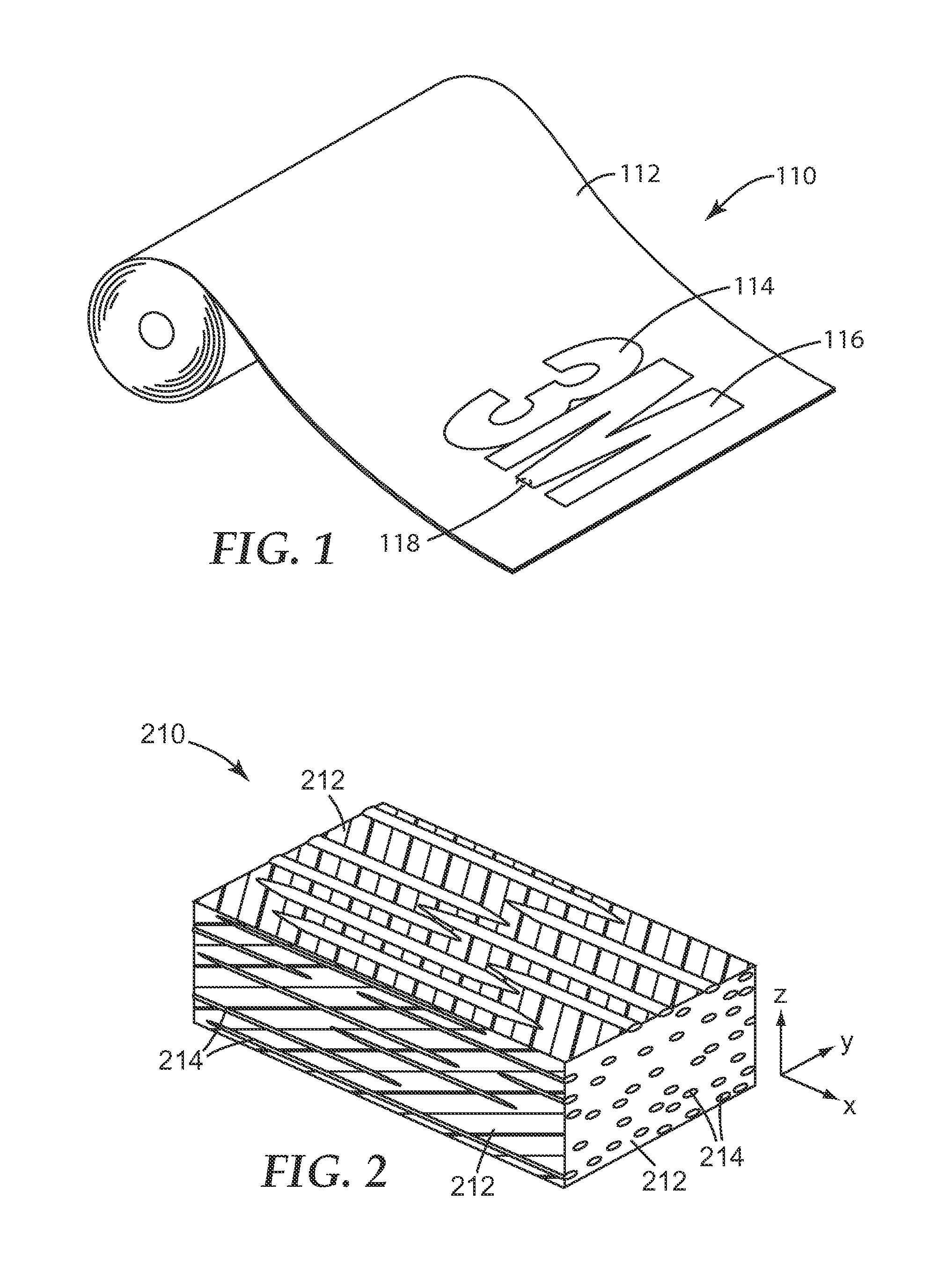
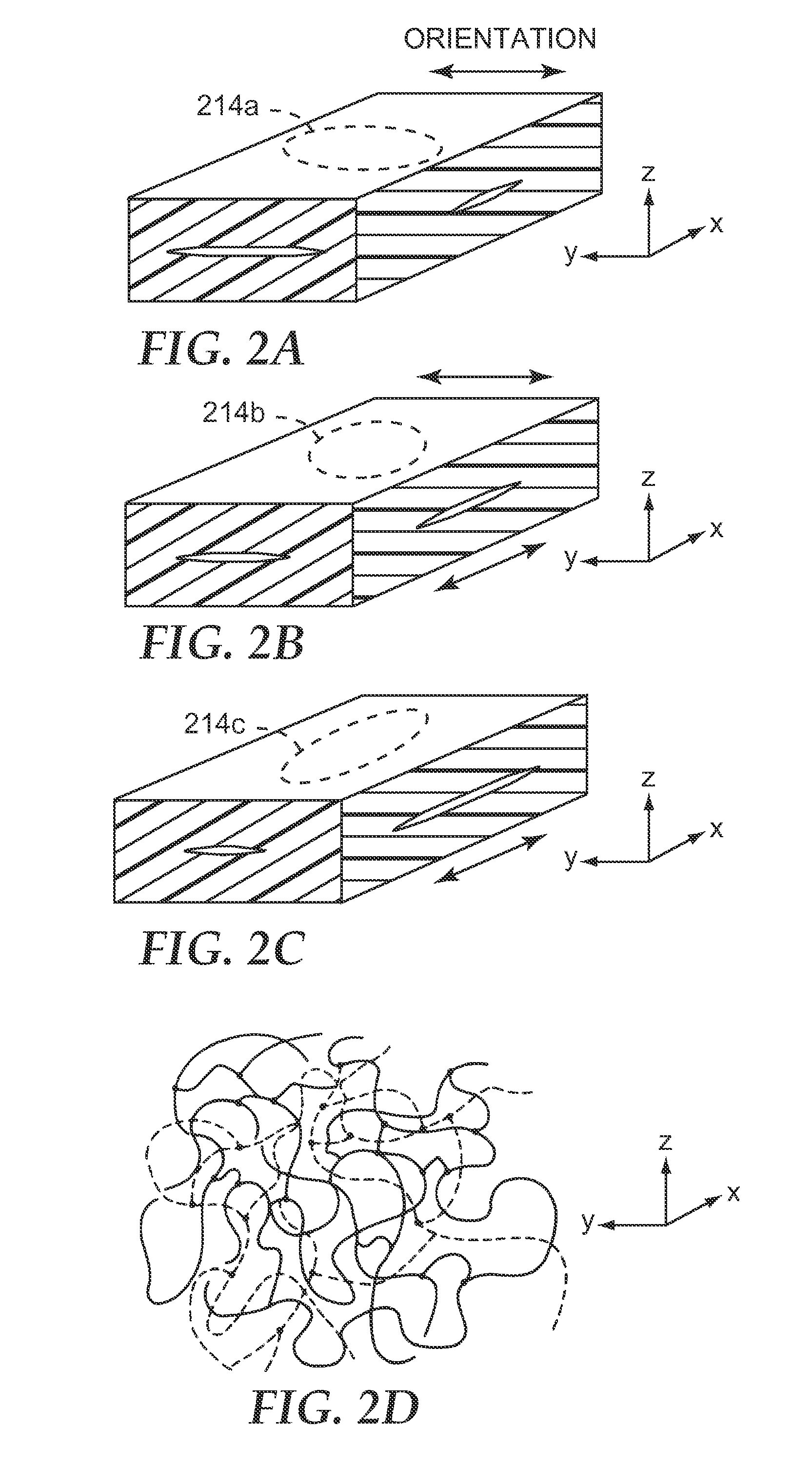
[0009]The selective birefringence reduction can be performed by the judicious delivery of an appropriate amount of energy to the second zone so as to selectively heat at least one of the blended polymer materials therein to a temperature high enough to produce a relaxation in the material that reduces or eliminates a preexisting optical birefringence. In some cases, the elevated temperature during heating may be low enough, and / or may persist for a brief enough time period, to maintain the physical integrity of the morphological blend structure within the film. In such cases, the blend morphology of the second zone is substantially unchanged by the selective heat treatment, even though the birefringence is reduced. The reduction in birefringence may be partial or it may be complete, in which case one or more polymer materials that are birefringent in the first zone are rendered optically isotropic in the second zone. In exemplary embodiments, the selective heating is achieved at least in part by selective delivery of light or other radiant energy to the second zone of the film. The light may comprise ultraviolet, visible, or infrared wavelengths, or combinations thereof. At least some of the delivered light is absorbed by the film to provide the desired heating, with the amount of light absorbed being a function of the intensity, duration, and wavelength distribution of the delivered light, and the absorptive properties of the film. Such a technique for internally patterning a blended film is compatible with known high intensity light sources and electronically addressable beam steering systems, thus allowing for the creation of virtually any desired pattern or image in the film by simply steering the light beam appropriately, without the need for dedicated hardware such as image-specific embossing plates or photomasks.

Problems solved by technology

A substantial mismatch in refractive index between the continuous phase polymer and the disperse phase polymer along a particular axis has the effect that incident light polarized along that axis will be substantially scattered, resulting in a significant amount of reflection.

Method used


Image

  • Diffuse reflective optical films with spatially selective birefringence reduction
  • Diffuse reflective optical films with spatially selective birefringence reduction
  • Diffuse reflective optical films with spatially selective birefringence reduction

Examples


example 1

[0163]A multi-layer optical film was co-extruded comprising an inner core (optical packet) and two outer, diffuse-reflective skin layers. The inner core comprised 151 alternating layers of a higher and lower refractive index polyester. The two outer layers of the optical core were thicker to form two protective boundary layers (PBLs). The PBLs comprised the lower index material. The higher index material was a copolymer of polyethylene naphthalate (PEN), and comprised 90 mol % naphthalene dicarboxylate and 10 mol % terephthalate as carboxylates as described in Example 1 of U.S. Pat. No. 6,352,761 (Hebrink et al.), this copolymer containing both PEN and polyethylene terephthalate (PET) sub-units, and referred to herein as 90 / 10 coPEN. The lower index material was another copolymer of PEN (i.e., another coPEN) as described in Example 10 of U.S. Pat. No. 6,352,761 (Hebrink et al.), this lower index material referred to herein as 55 / 45 HD coPEN. The skin layers of the multilayer optical...


PUM


Abstract

A diffusely reflective optical film includes a blended layer extending from a first to a second zone of the film. The blended layer includes first and second polymer materials separated into distinct first and second phases, respectively. The blended layer may have the same composition and thickness in the first and second zones, but different first and second diffusely reflective characteristics in the first and second zones, respectively. The difference between the first and second diffusely reflective characteristics may not be attributable to any difference in composition or thickness of the layer between the first and second zones. Instead, the difference between the first and second diffusely reflective characteristic may be attributable to a difference in birefringence of the first and/or second polymer materials between the first and second zones. The blend morphology of the blended layer may be substantially the same in the first and second zones.

Description

FIELD OF THE INVENTION[0001]This invention relates generally to optical films, and associated systems and methods.BACKGROUND[0002]Diffusely reflective polymer-based optical films are known. For example, U.S. Pat. Nos. 5,825,543 (Ouderkirk et al.) and 7,057,816 (Allen et al.) describe, among other things, optical films with a disperse phase of polymeric particles disposed within a continuous birefringent matrix of another polymeric material. The films are oriented, typically by stretching, in one or more directions. The size and shape of the disperse phase particles, the volume fraction of the disperse phase, the film thickness, and the amount of orientation are chosen to attain a desired degree of diffuse reflection and total transmission of electromagnetic radiation of a desired wavelength in the resulting film. A substantial mismatch in refractive index between the continuous phase polymer and the disperse phase polymer along a particular axis has the effect that incident light po...

Claims


Application Information

Patent Timeline
Patent Type & Authority Applications(United States)
IPC IPC(8): G02B5/02
CPCB42D2033/18B42D2033/30B42D2035/20B44F1/02G02B5/0242G02B5/3008B42D25/391G02B5/02B42D25/41B42D25/29B42D25/00B42D25/382G02B5/305B42D15/00G02B5/08B42D25/45B42D25/387
Inventor MERRILL, WILLIAM WARD
Owner 3M INNOVATIVE PROPERTIES CO
Why Eureka
Try Eureka