X ray source grating stepping imaging system and image method

a technology of stepping imaging system and x-ray source, applied in the field of xray imaging, can solve the problems of difficult to obtain a clear image, difficult to produce the required optical elements, and many imperfections

Active Publication Date: 2013-04-18
TSINGHUA UNIV +1
View PDF1 Cites 34 Cited by
  • Summary
  • Abstract
  • Description
  • Claims
  • Application Information

AI Technical Summary

Benefits of technology

[0008]Wherein, said system further comprises an actuation means for enabling the source grating to perform stepping movement, and/or enabling the object to be detected to rotate by an angle relative to other parts of the system under the control of the computer workstation. The stepping process of the source grating is repeated at each rotation angle, thereby obtaining X-ray imaging pixel values at multiple angles, and then a stereo image of the detected object is reconstructed according to a predetermined CT image reconstruction algorithm.
[0009]Wherein, said computer workstation

Problems solved by technology

It is also difficult to obtain a clear image even if other auxiliary means are used, such as injecting contrast agent into biological tissues, which results in a lot of imperfections.
As for the dark-field imaging, due to the unique optical properties of hard X-ray, it is very difficult to produce the required optical elements, thus the hard X-ray dark-field imaging is always hard to achieve well.
Since the phase grating, parse grating or

Method used


Image

  • X ray source grating stepping imaging system and image method
  • X ray source grating stepping imaging system and image method
  • X ray source grating stepping imaging system and image method

Examples


Embodiment Construction

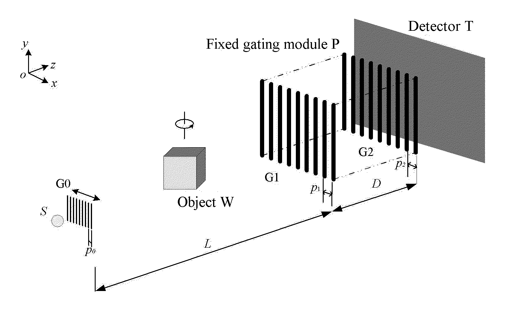
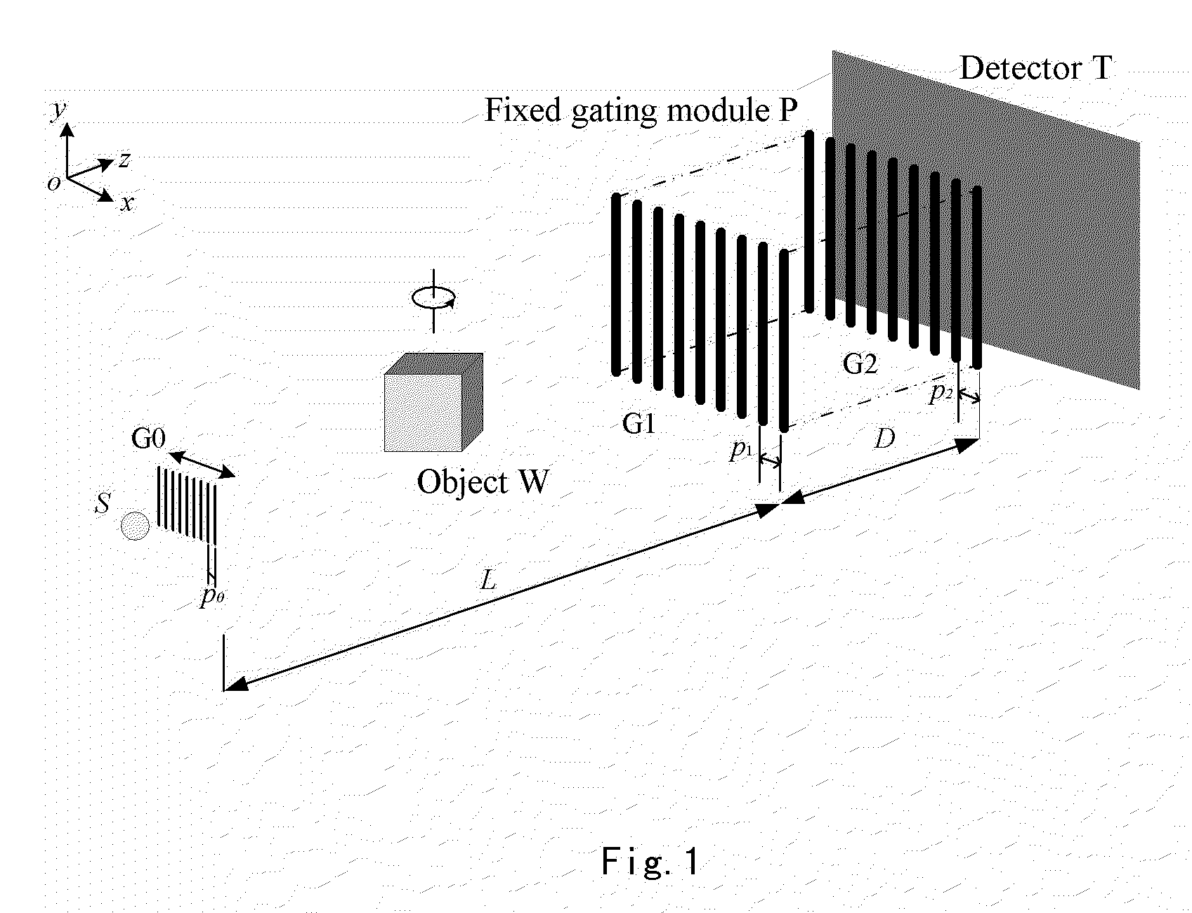
[0025]As shown in FIG. 1, according to the principle of the present invention, an X-ray imaging system essentially consists of: an X-ray machine S, a movable source grating G0, a fixed grating module P (including a first grating G1 and a second grating G2), and an X-ray detector T, which are successively positioned in the propagation direction of the emitted X-ray. An object to be detected is positioned between said source grating G0 and said fixed grating module.

[0026]Wherein the X-ray machine serving as an X-ray source may be a general X-ray machine used in current medical devices, which is usually a high-current pulse-mode X-ray machine suitable for imaging galactophore and may comprise corresponding auxiliary devices. The X-ray machine is used for emitting X-ray beams to the object to be detected. Generally speaking, the auxiliary devices include a filter. A medical X-ray machine has a working voltage usually set between 5 and 160 kVp. The X-ray beams emitted by the general X-ra...


PUM


Abstract

An X-ray imaging system comprising: an X-ray source, a source grating, a fixed grating module and an X-ray detector, which are successively positioned in the propagation direction of X-ray; an object to be detected is positioned between the source grating and the fixed gating module; said source grating can perform stepping movement in a direction perpendicular to the optical path and grating stripes; wherein the system further comprises a computer workstation for controlling said X-ray source, source grating and X-ray detector so as to perform the following processes: the source grating performs stepping movement in at least one period thereof; at each stepping step, the X-ray source emits X-ray to the object to be detected, and the detector receives the X-ray at the same time; wherein after at least one period of stepping and data acquisition, the light intensity of X-ray at each pixel point on the detector is represented as a light intensity curve; the light intensity curve at each pixel point on the detector is compared with a light intensity curve in the absence of the object to be detected, a pixel value of each pixel point is calculated from change in said light intensity curve; an image of the detected object is reconstructed according to the calculated pixel value.

Description

TECHNICAL FIELD[0001]The present invention generally relates to an X-ray imaging field, more specifically to projection imaging of an object using X-ray through a grating stepping technology.BACKGROUND ART[0002]In the prior art such as a CT scanning device, scan imaging of an object using X-ray has been widely used. Traditional X-ray scan imaging generally makes use of attenuation characteristics of the detected material to X-ray so as to examine the internal structure of the object in a nondestructive way. If the structural constitutions of respective parts inside the object are notably different in density, the effect of the traditional X-ray imaging technology is especially significant. As for substances consisting of light elements, they are weak-absorbing substances for X-ray, thus the internal specific structures thereof almost cannot be seen by means of the traditional X-ray imaging technology. It is also difficult to obtain a clear image even if other auxiliary means are use...

Claims


Application Information

Patent Timeline
IPC IPC(8): G01N23/04G03B42/02
CPCA61B6/484G01N2223/419A61B6/4291G01N23/046
Inventor HUANG, ZHIFENGCHEN, ZHIQIANGZHANG, LILI, YUANJINGXING, YUXIANGZHAO, ZIRANXIAO, YONGSHUNLI, LIANGDING, FEI
Owner TSINGHUA UNIV
Why Eureka
Try Eureka