Fuel cell and method of operating the fuel cell
- Summary
- Abstract
- Description
- Claims
- Application Information
AI Technical Summary
Benefits of technology
Problems solved by technology
Method used
Image

Examples
first embodiment
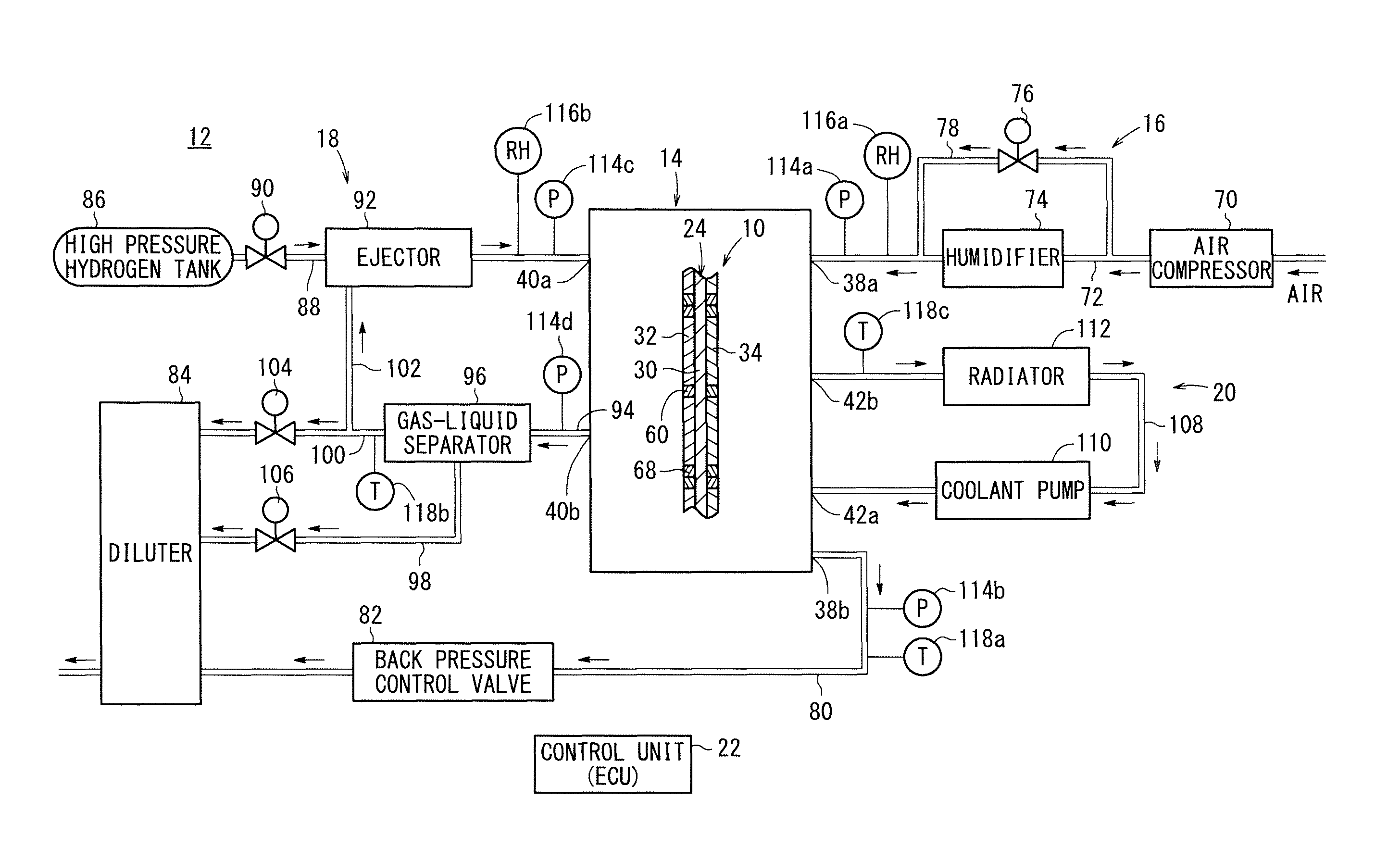
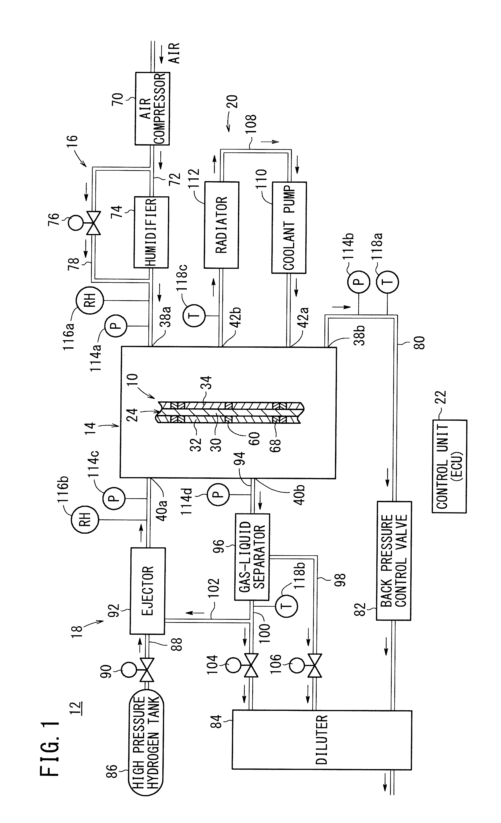
[0043]In FIG. 1, a fuel cell system 12 in which a method of operating a fuel cell 10 according to the present invention is performed is a fuel cell system mounted in a vehicle. For example, the fuel cell system 12 is mounted in a fuel cell vehicle such as a fuel cell electric vehicle.
[0044]The fuel cell system 12 includes a fuel cell stack 14 formed by stacking a plurality of the fuel cells 10, an oxygen-containing gas supply apparatus 16 for supplying an oxygen-containing gas to the fuel cell stack 14, a fuel gas supply apparatus 18 for supplying a fuel gas to the fuel cell stack 14, a coolant supply apparatus 20 for supplying a coolant to the fuel cell stack 14, and a control unit (ECU) 22 for controlling the entire fuel cell system 12.
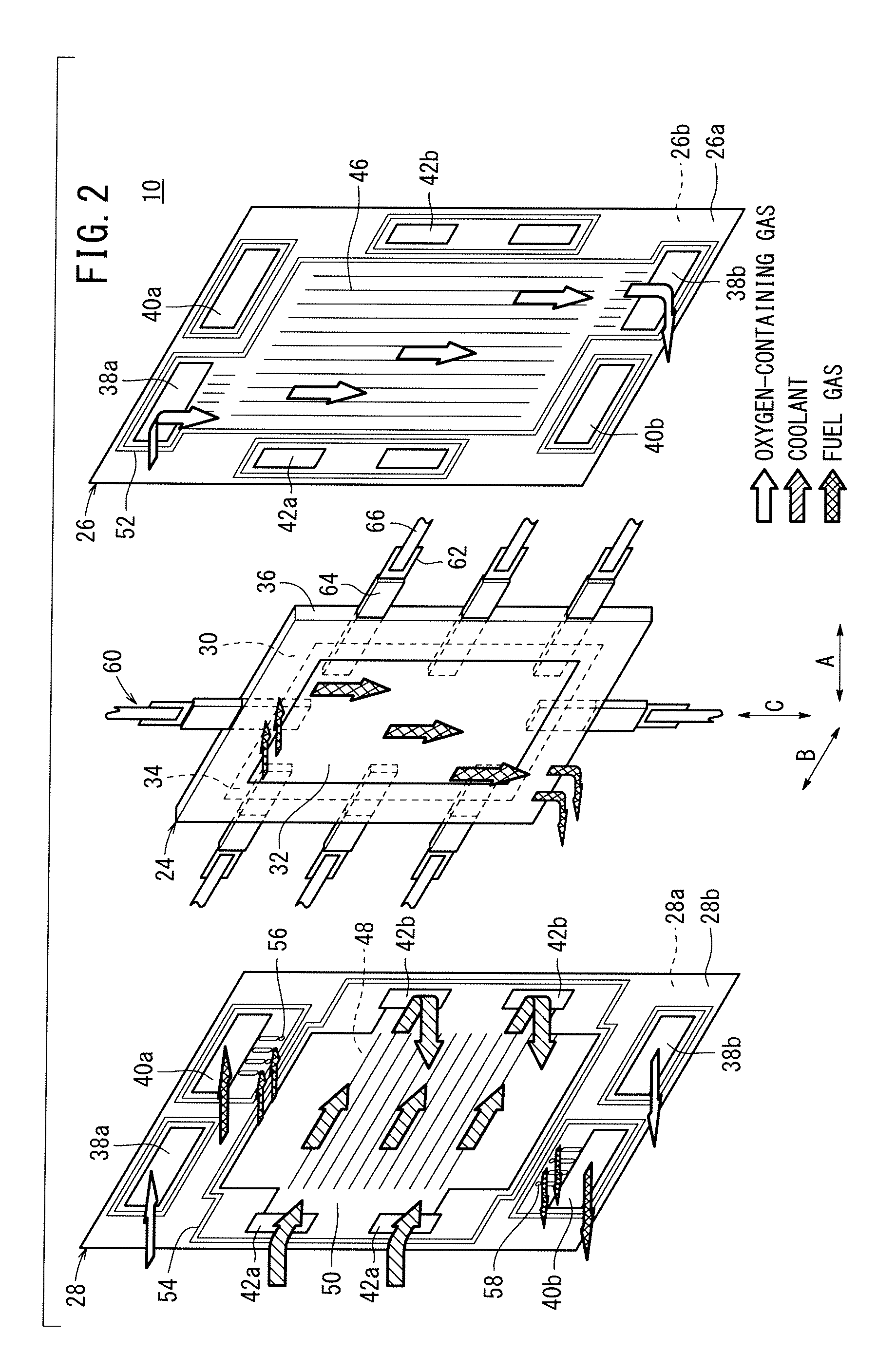
[0045]As shown in FIG. 2, each of the fuel cells 10 includes a membrane electrode assembly 24 and a first separator 26 and a second separator 28 sandwiching the membrane electrode assembly 24. For example, the first separator 26 and the second separ...
second embodiment
[0102]Therefore, in the operating method according to the present invention, control shown in FIG. 19 is implemented. That is, during steady power generation operation, for example, if water condensation occurs in the gas channel, and a change in the hydrogen peroxide concentration is detected, desired operation control is implemented based on a map (see FIG. 14) which has been stored beforehand. Specifically, when decrease in the hydrogen peroxide concentration is detected, in order to suppress the increase in the electric potential, for example, control to increase the flow rate of the fuel gas, control to increase the flow rate of the oxygen-containing gas, control to decrease the humidity of the reactant gases supplied to the cathode and the anode, and additionally, though not shown, control to increase the coolant temperature are implemented in combination (restoration control). Therefore, it is possible to effectively suppress generation of active substances due to the increas...
PUM
 Abstract
Description
Claims
Application Information
 - R&D
- Intellectual Property
- Life Sciences
- Materials
- Tech Scout
- Unparalleled Data Quality
- Higher Quality Content
- 60% Fewer Hallucinations
Browse by: Latest US Patents, China's latest patents, Technical Efficacy Thesaurus, Application Domain, Technology Topic, Popular Technical Reports.
© 2025 PatSnap. All rights reserved.Legal|Privacy policy|Modern Slavery Act Transparency Statement|Sitemap|About US| Contact US: help@patsnap.com