Method of controlling a combustion engine from estimation of the burnt gas mass fraction in the intake manifold

Inactive Publication Date: 2013-04-18
INST FR DU PETROLE
View PDF14 Cites 4 Cited by
  • Summary
  • Abstract
  • Description
  • Claims
  • Application Information

AI Technical Summary

Benefits of technology

[0020]According to another embodiment, combustion control is achieved by controlling an air mass contained in the cylinder, by controllin

Problems solved by technology

However, using such a technology greatly increases the risk of engine knock appearance.
When the engine runs under full load conditions, the thermodynamic conditions in the combustion chamber may be detrimental to the stability of the mixture and generate auto-ignition thereof.
This phenomenon can eventually greatly deteriorate the comb

Method used


Image

  • Method of controlling a combustion engine from estimation of the burnt gas mass fraction in the intake manifold
  • Method of controlling a combustion engine from estimation of the burnt gas mass fraction in the intake manifold
  • Method of controlling a combustion engine from estimation of the burnt gas mass fraction in the intake manifold

Examples


Example

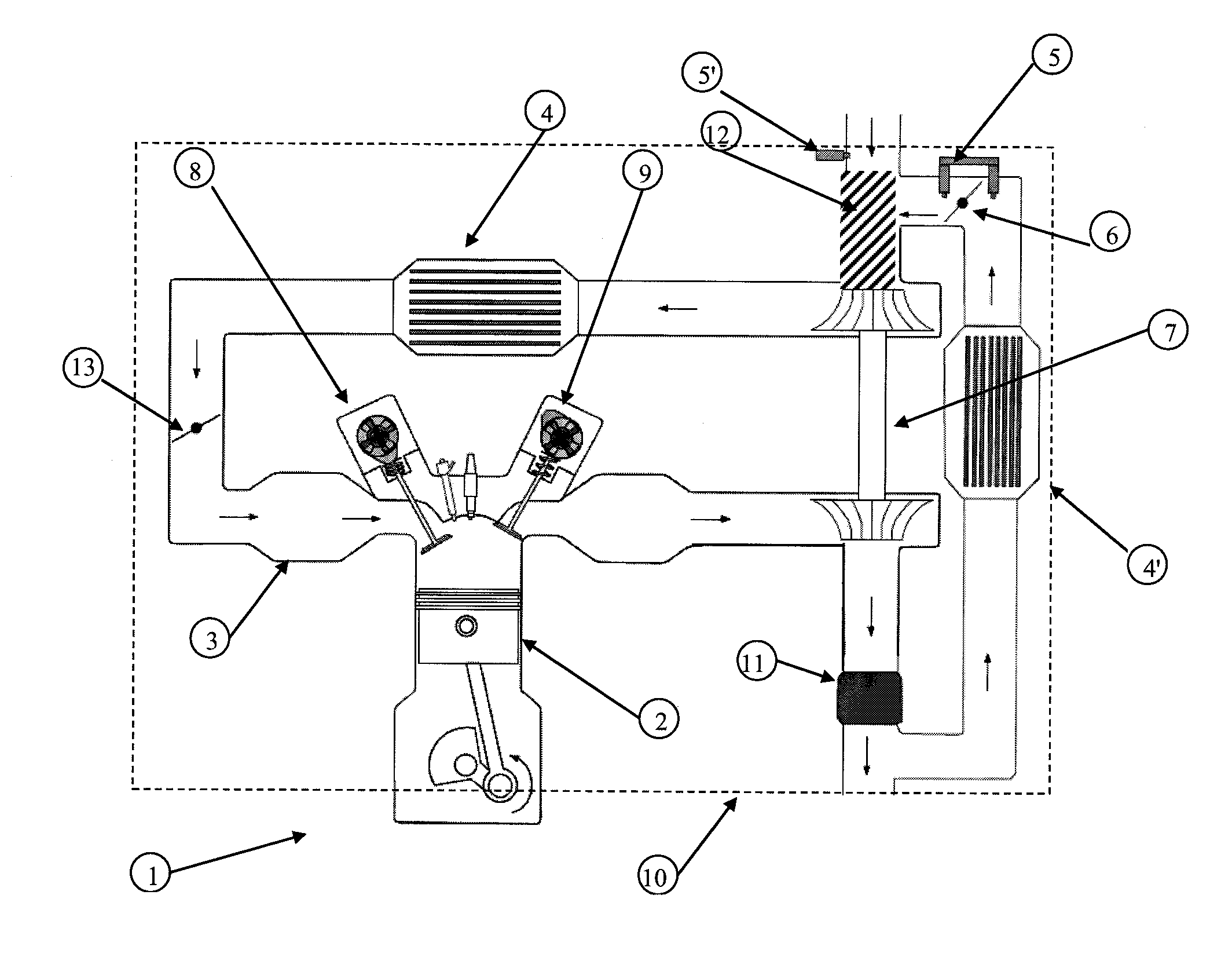
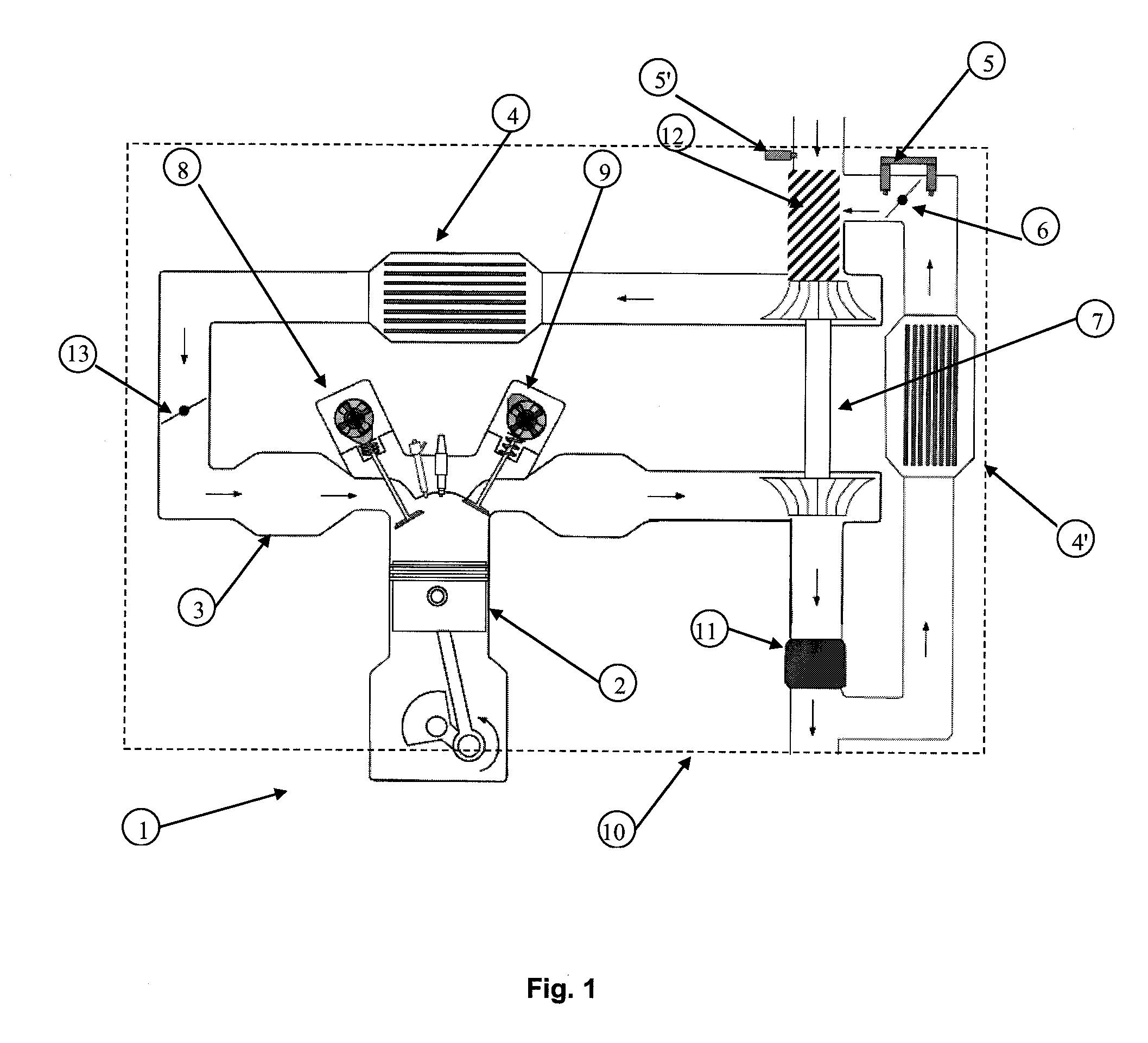
[0026]FIG. 1 shows a gasoline engine (1) provided with an EGR burnt gas recirculation circuit. At least one cylinder (2) of combustion engine (1) is supplied with air and burnt gas from an intake manifold (3). The air intake circuit is provided with a cooler (4) and a turbocharger (7) compressor. The exhaust line consists of an exhaust manifold (13), a turbocharger (7) turbine, a bypass line, for injecting part of the burnt gas into the air intake circuit. This part of the circuit is notably provided with a cooler (4′) and a controlled valve, referred to as EGR valve (6), which controls the amount of burnt gas injected into the air intake circuit. This engine is in particular equipped with either a pressure difference detector (5) at the level of the EGR valve or an air flow meter (5′) at the start of the intake line. Engine (1) as shown in FIG. 1 is also provided with a direct injection device and a variable valve timing system, these elements being usually present in a downsized e...


PUM


Abstract

In a method of controlling the combustion of a combustion engine from an estimation of the burnt gas mass fraction in the intake manifold, a measurement relative to a fresh air flow rate or to a burnt gas flow rate is performed upstream from the mixing space where fresh air and burnt gas mix. The burnt gas mass fraction present in the mixing space is then estimated from the measurement and from a model of the mixing dynamics in this space. A transport delay between the space and the intake manifold is estimated. The mass fraction of burnt gas in the intake manifold is then deduced in real time. Finally, combustion is controlled from the burnt gas mass fraction in the intake manifold.

Description

FIELD OF THE INVENTION[0001]The present invention relates to the sphere of engine control and more particularly to the estimation of the burnt gas recirculation rate for a gasoline engine provided with an EGR circuit.BACKGROUND OF THE INVENTION[0002]Downsizing gasoline engines currently appears to be the preferred option for reducing the consumption of gasoline engines. In fact, this technology allows to shift the working points of the engine to zones of higher efficiency and thus to limit the pumping losses inherent in the operation of an internal-combustion engine. This type of engine then requires the presence of a compressor driven by a turbine arranged in the exhaust line. Such a device is used to improve air filling of the cylinder and to provide a torque equivalent to that of an engine of conventional displacement. It is thus possible to have the same performances while drastically reducing the consumption.[0003]However, using such a technology greatly increases the risk of e...

Claims


Application Information

Patent Timeline
IPC IPC(8): G06F7/00
CPCF02D41/0072F02D41/18Y02T10/47F02D2041/0075F02D2041/1433F02D41/0007Y02T10/40
Inventor BRESCH-PIETRI, DELPHINELEROY, THOMASCHAUVIN, JONATHAN
Owner INST FR DU PETROLE
Why Eureka
Try Eureka