Nyquist Constrained Digital Finite Impulse Response Filter

a digital finite impulse and filter technology, applied in the field of nyquist constrained can solve the problems of time-consuming and complicated meeting of other objectives, and achieve the effect of frequency response sensitivity of the digital finite impulse response filter to the variable sampling phas

Inactive Publication Date: 2013-04-18
AVAGO TECH INT SALES PTE LTD
View PDF3 Cites 8 Cited by
  • Summary
  • Abstract
  • Description
  • Claims
  • Application Information

AI Technical Summary

Benefits of technology

[0006]In some instances of the aforementioned embodiments, the apparatus includes an analog to digital converter with a variable sampling phase connected to an input of the digital finite impulse r...

Problems solved by technology

However, DFIR filters may be sensitive to the selection of the ADC sampling phase, yielding various frequency responses to different ADC sampling phases.
Adjusting the ADC sampling phase based ...

Method used


Image

  • Nyquist Constrained Digital Finite Impulse Response Filter
  • Nyquist Constrained Digital Finite Impulse Response Filter
  • Nyquist Constrained Digital Finite Impulse Response Filter

Examples


Embodiment Construction

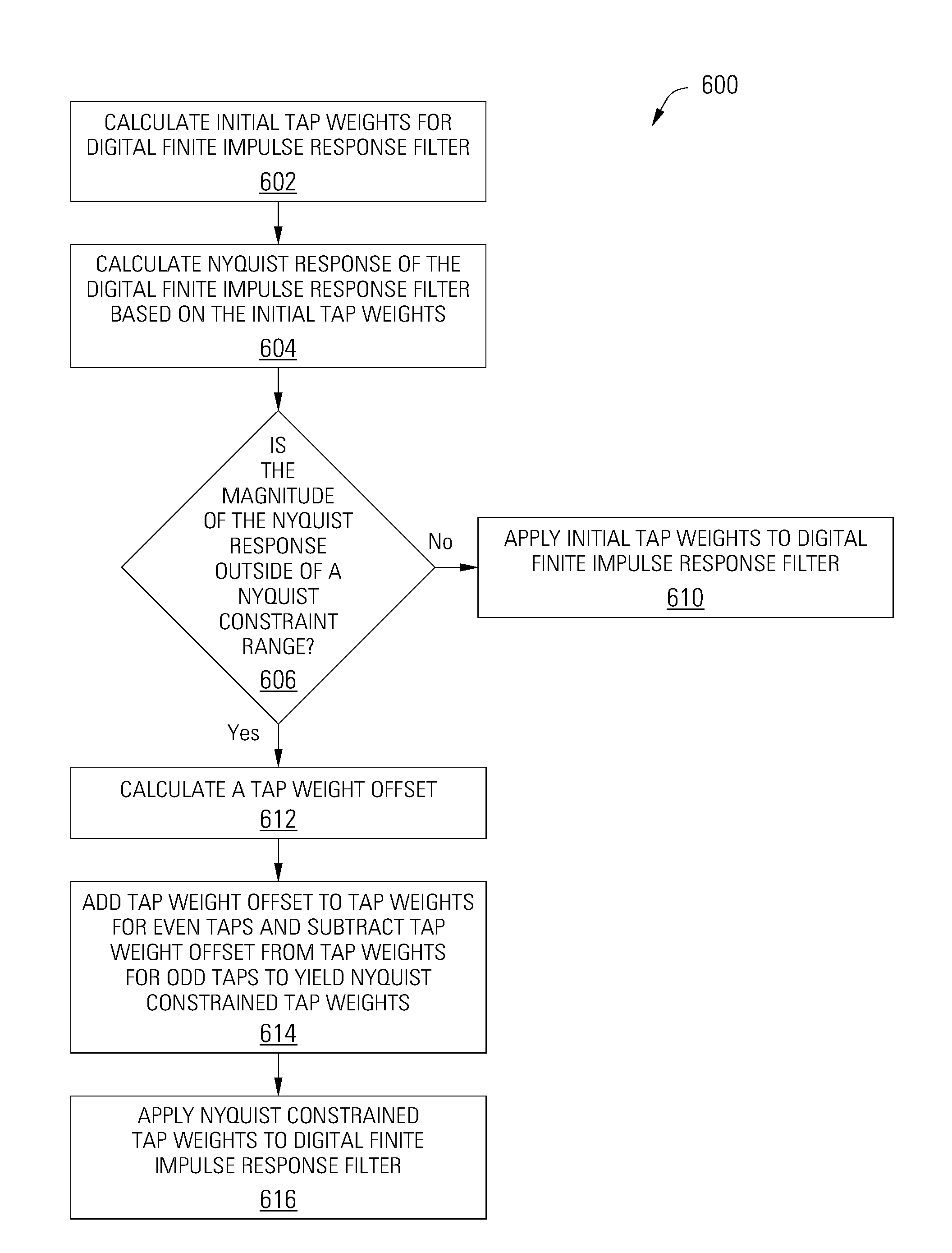
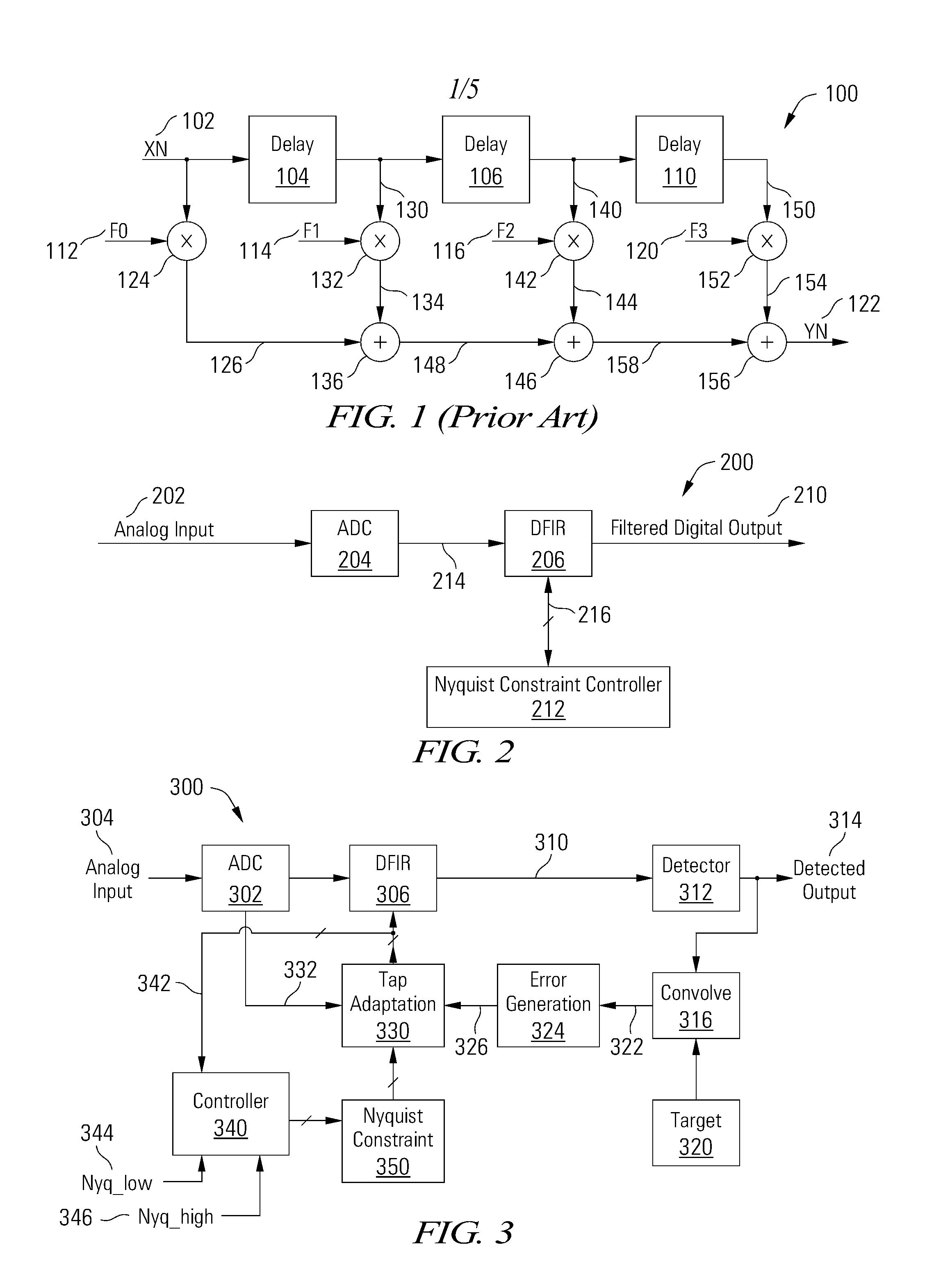
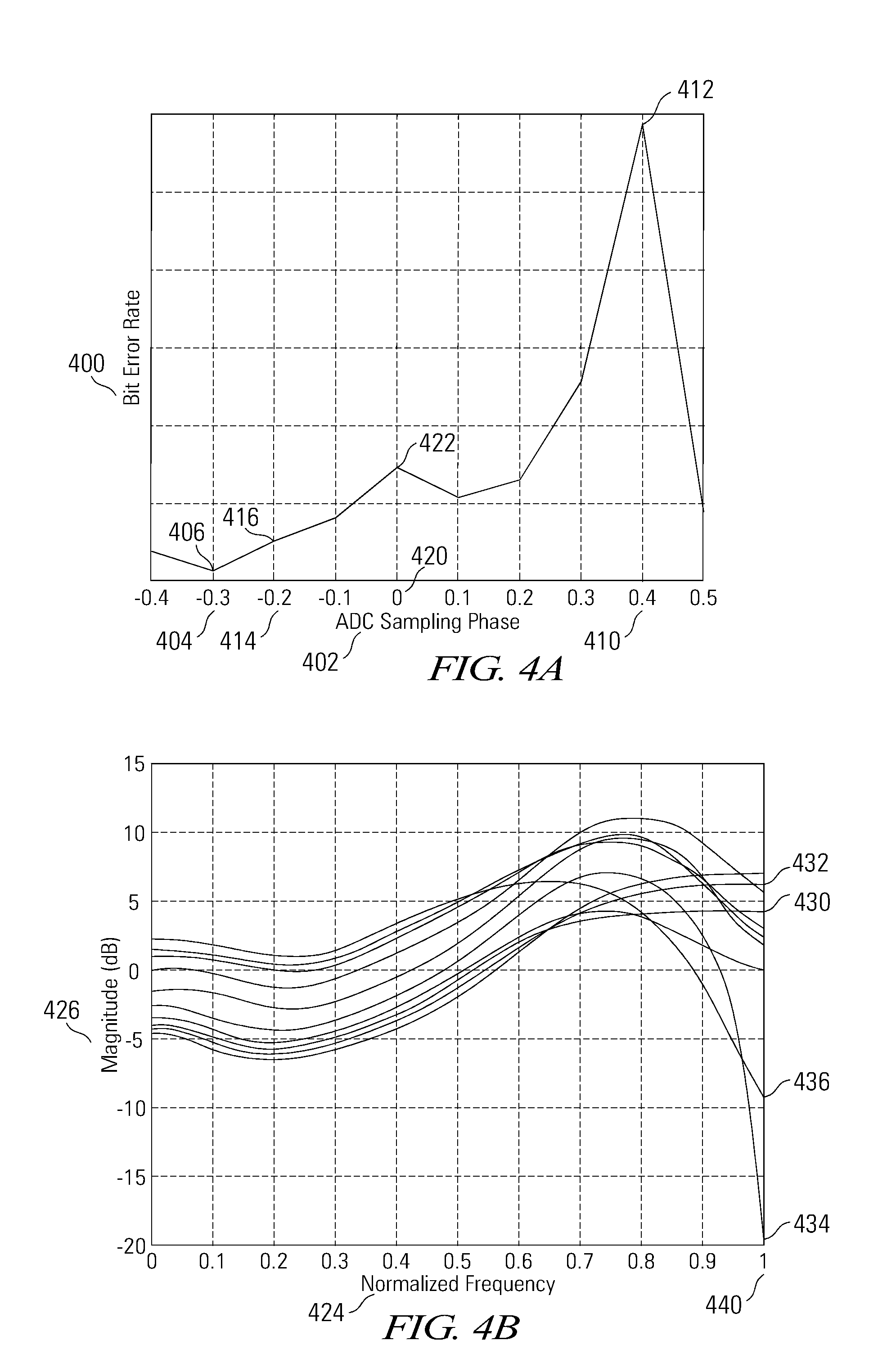
[0020]Various embodiments of the present invention are related to apparatuses and methods for filtering a digital signal, and more particularly to a Nyquist constrained DFIR filter. Various embodiments of the present invention constrain the magnitude of the Nyquist response of a DFIR filter to remain within a Nyquist constraint range. When the magnitude of the Nyquist response remains within the range, the sensitivity of the DFIR filter to an upstream ADC sampling phase is greatly reduced. The Nyquist response and the magnitude of the Nyquist response of the DFIR filter at time k are represented by S and by |S|, respectively, and are defined herein by Equations 1 and 2:

S=∑i(f2i,k-f2i+1,k)Equation1S=∑i(f2i,k-f2i+1,k)Equation2

[0021]where S is the sum of the even tap weights minus the odd tap weights and |S| is the absolute value of S, where f2i,k represents the even tap weights (e.g., 112, 116) and f2i+1,k represents the odd tap weights (e.g., 114, 120). The tap weights may originally...


PUM


Abstract

Various embodiments of the present invention provide apparatuses and methods for filtering a digital signal with a Nyquist constrained digital finite impulse response filter. For example, an apparatus for filtering digital data is disclosed that includes a digital finite impulse response filter having a plurality of taps. The apparatus also includes a tap weight controller connected to the digital finite impulse response filter, operable to adjust a tap weight for each of a subset of the taps such that a magnitude of a Nyquist response of the digital finite impulse response filter remains within a constraint range.

Description

BACKGROUND[0001]Filters are commonly used in electronic systems such as signal processing and data processing circuits to remove noise from a data signal. A digital finite impulse response (DFIR) filter applies a mathematical operation to a digital data stream to achieve any of a wide range of desired frequency responses. As illustrated in FIG. 1, a DFIR filter 100 passes an input 102 through a series of delay elements 104, 106 and 110, multiplying the delayed signals by filter coefficients or tap weights 112, 114, 116 and 120, and summing the results to yield a filtered output 122. The outputs 130, 140 and 150 of each delay element 104, 106 and 110 and the input 102 form a tapped delay line and are referred to as taps. The number of delay elements 104, 106 and 110, and thus the number of taps 102, 130, 140 and 150 (also referred to as the order or length of the DFIR filter 100) may be increased to more finely tune the frequency response, but at the cost of increasing complexity. Th...

Claims


Application Information

Patent Timeline
IPC IPC(8): G06F17/10
CPCH03H17/06G06F17/15H03H2017/0222
Inventor LIAO, YUSONG, HONGWEILIU, JINGFENGZHANG, HAOTIAN
Owner AVAGO TECH INT SALES PTE LTD
Why Eureka
Try Eureka