Display device

a display device and display body technology, applied in the field of display devices, can solve the problems of difficult to achieve a large screen, and the main body of the device is compact in size, and achieves the effect of large screen size and compact main body siz

Inactive Publication Date: 2013-04-25
PANASONIC INTELLECTUAL PROPERTY MANAGEMENT CO LTD
View PDF9 Cites 33 Cited by
  • Summary
  • Abstract
  • Description
  • Claims
  • Application Information

AI Technical Summary

Benefits of technology

[0010]The present invention resolves the aforementioned conventional problems, an object thereof being to provide a display device which achieves both a co

Problems solved by technology

However, in the conventional optical enlarging method described above, in order to make the main body of the device compact, a compact liquid crystal panel is arranged close to the user's eye, while a virtual screen which is displayed to the user is displayed larger than the liquid crystal panel size and at a further distance than the liquid crystal panel, but since the enlarging optical system becomes large in size, then it has been difficult to achieve

Method used


Image

  • Display device
  • Display device
  • Display device

Examples


first embodiment

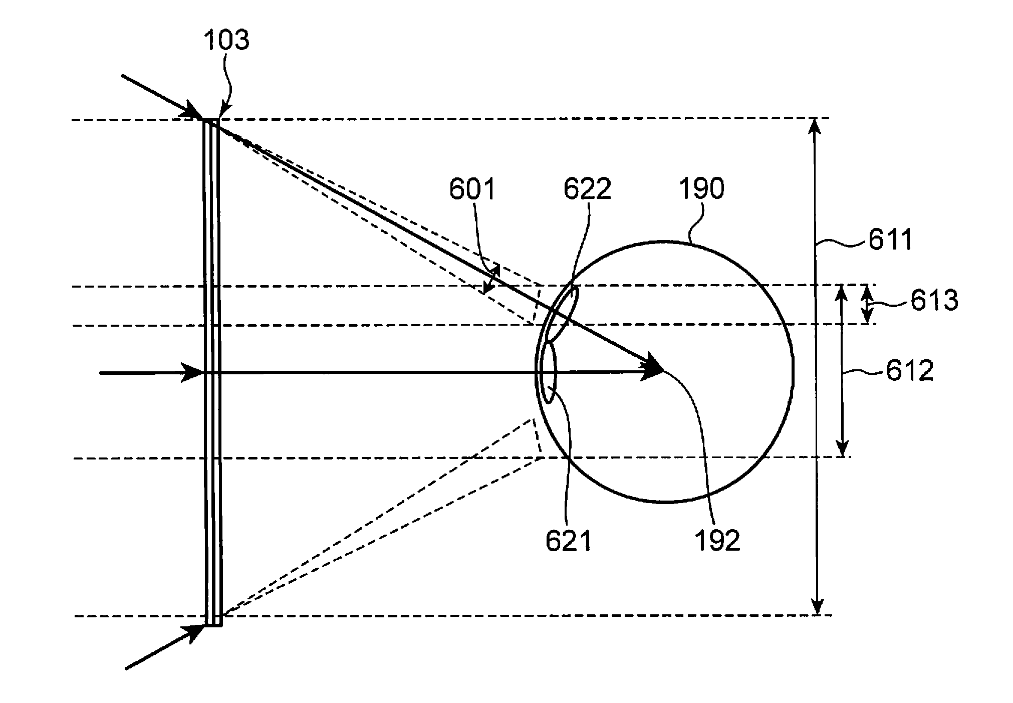
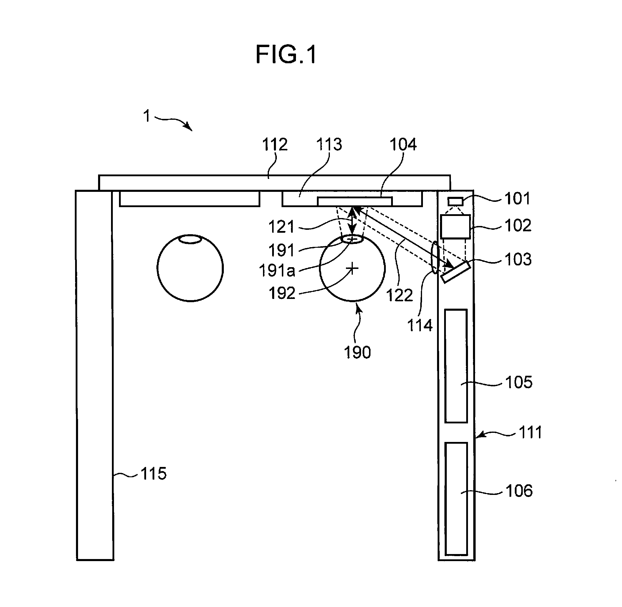
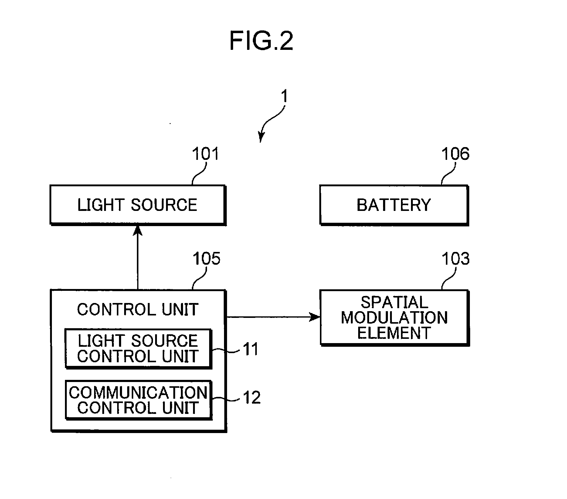
[0031]FIG. 1 is a diagram showing a schematic view of the composition of a display device 1 according to a first embodiment of the present invention. FIG. 2 is a block diagram showing an electrical composition of the display device 1 shown in FIG. 1. FIG. 3 is a diagram showing an illumination optical system which illuminates a spatial modulation element of the display device 1 shown in FIG. 1. FIG. 4 is a diagram showing a composition of a reflecting mirror of the display device 1 shown in FIG. 1. FIG. 5 is a diagram showing an emission aperture of the display device 1 shown in FIG. 1. The display device 1 according to the first embodiment has the form of glasses, and FIG. 1 is a view observed from above.

[0032]In FIG. 1, the light source 101 is a laser light source which outputs laser light. In FIG. 1, a semiconductor laser (laser diode) which outputs laser light of a green wavelength is used as the light source. The laser light may be red or blue monochrome light, or a color displ...

second embodiment

[0098]FIG. 10 is a block diagram showing an electrical composition of a display device according to a second embodiment of the present invention. In the second embodiment, elements which are similar to the first embodiment are labeled with the same reference numerals. Below, the second embodiment is described with particular reference to the points of difference with respect to the first embodiment.

[0099]In the display device 1a according to the second embodiment shown in FIG. 10, the control unit 105 includes an element control unit 13 instead of the communication control unit 12, in comparison with the display device 1 according to the first embodiment shown in FIG. 2. The composition of the second embodiment other than this is the same as the first embodiment.

[0100]The element control unit 13 calculates a diffraction pattern (a diffraction pattern 402 which is shown in FIG. 8B, for instance), from a desired fictive image (the fictive image 401 shown in FIG. 8A, for instance). The...

third embodiment

[0103]FIG. 11 is a block diagram showing an electrical composition of a display device according to a third embodiment of the present invention. In the third embodiment, elements which are similar to the first and second embodiments are labeled with the same reference numerals. Below, the third embodiment is described with particular reference to the points of difference with respect to the first and second embodiments.

[0104]The display device 1b according to the third embodiment shown in FIG. 11 includes an element control unit 13a instead of the communication control unit 12, and also includes a diffraction angle information acquisition unit 107, in comparison with the display device 1 according to the first embodiment shown in FIG. 2. The composition of the third embodiment other than this is the same as the first embodiment.

[0105]The diffraction angle information acquisition unit 107 acquires information relating to variation in the diffraction angle in the spatial modulation el...


PUM


Abstract

A display device (1) includes a light source (101) which outputs laser light, an illumination optical system (102) which emits the laser light as illumination light, a spatial modulation element (103) which diffracts the illumination light by displaying a diffraction pattern, and a wearing section (111) for wearing on a user's head. A positional relationship between the spatial modulation element (103) and an expected eye position (191a), which is expected to be a position of an eye (190) of the user, is fixed in a state where the wearing section (111) is worn on the user's head. The spatial modulation element (103) displays, as the diffraction pattern, a diffraction pattern by which a fictive image is displayed to the user due to diffracted light, which has been diffracted by the diffraction pattern, reaching the expected eye position (191a).

Description

TECHNICAL FIELD[0001]The present invention relates to a head-mounted type display device which displays information by diffracting laser light by a diffraction pattern based on a computer generated hologram.BACKGROUND ART[0002]A head-mounted display (hereinafter called “HMD”) is a device which displays information to a user while being mounted on the user's head. Desirably, an HMD is compact and lightweight, from the viewpoint of wearability, but has a large screen for high image quality, from the viewpoint of display characteristics. Conventionally, in an HMD, an enlarged fictive image is displayed to the user by optically enlarging an image displayed on a small liquid crystal panel, or the like, by means of a convex lens or free-form surface prism, or the like (hereinafter, called “optical enlarging method”). For example, the “image display device” according to Patent Document 1 is one HMD based on an optical enlarging method.[0003]Furthermore, in a display device which uses a com...

Claims


Application Information

Patent Timeline
IPC IPC(8): G03H1/08
CPCG02B27/017G02B2027/0178G02F2203/12G02B2027/0123G03H1/2294G03H2210/32G03H2227/02G03H1/2205
Inventor YAMAMOTO, KAKUYAKASAZUMI, KENICHISUGIYAMA, KEIJI
Owner PANASONIC INTELLECTUAL PROPERTY MANAGEMENT CO LTD
Why Eureka
Try Eureka