
Method for operating a fuel cell and fuel cell system with improved thermal control

a fuel cell and thermal control technology, applied in the direction of transportation fuel cell technology, electric hydrogen generators, transportation, etc., can solve the problems of limited waste heat generation, waste heat produced in motor vehicles can only be effective in some circumstances, and the consumption of vehicles, so as to increase the waste heat of the fuel cell, the effect of sufficient heating of the system and sufficient heatability of the passenger interior

Inactive Publication Date: 2013-04-25
ROBERT BOSCH GMBH
View PDF3 Cites 4 Cited by
  • Summary
  • Abstract
  • Description
  • Claims
  • Application Information

AI Technical Summary

Benefits of technology

The present invention is about reducing the efficiency of a fuel cell in a targeted manner to increase waste heat. This can be useful in various ways, such as improving safety and comfort in a vehicle equipped with a fuel cell system. By doing so, the system can make a significant contribution without requiring complex additional assemblies and reducing weight and consumption. Additionally, the reliability of the fuel cell system is improved since additional component parts always have the risk of damage or failure.

Problems solved by technology

Furthermore, fuel cells can provide improved efficiency primarily in the partial load range in comparison with internal combustion engines, which can become noticeable in the consumption of the vehicle.
Owing to the good efficiency of fuel cells, the waste heat produced for example in the case of motor vehicles can under some circumstances only actually be sufficient for heating the driver's cab and / or keeping the fuel cell system warm, for example.
In detail, under some circumstances in fuel cell systems which are operated over a relatively long period of time in the lower load range or under partial load, waste heat is only generated to a limited degree with electrical energy conversion.
As a result, the driver's cab is under some circumstances only heatable to a limited extent or the fuel cell system can cool down.

Method used


Image

  • Method for operating a fuel cell and fuel cell system with improved thermal control
  • Method for operating a fuel cell and fuel cell system with improved thermal control

Examples


Embodiment Construction

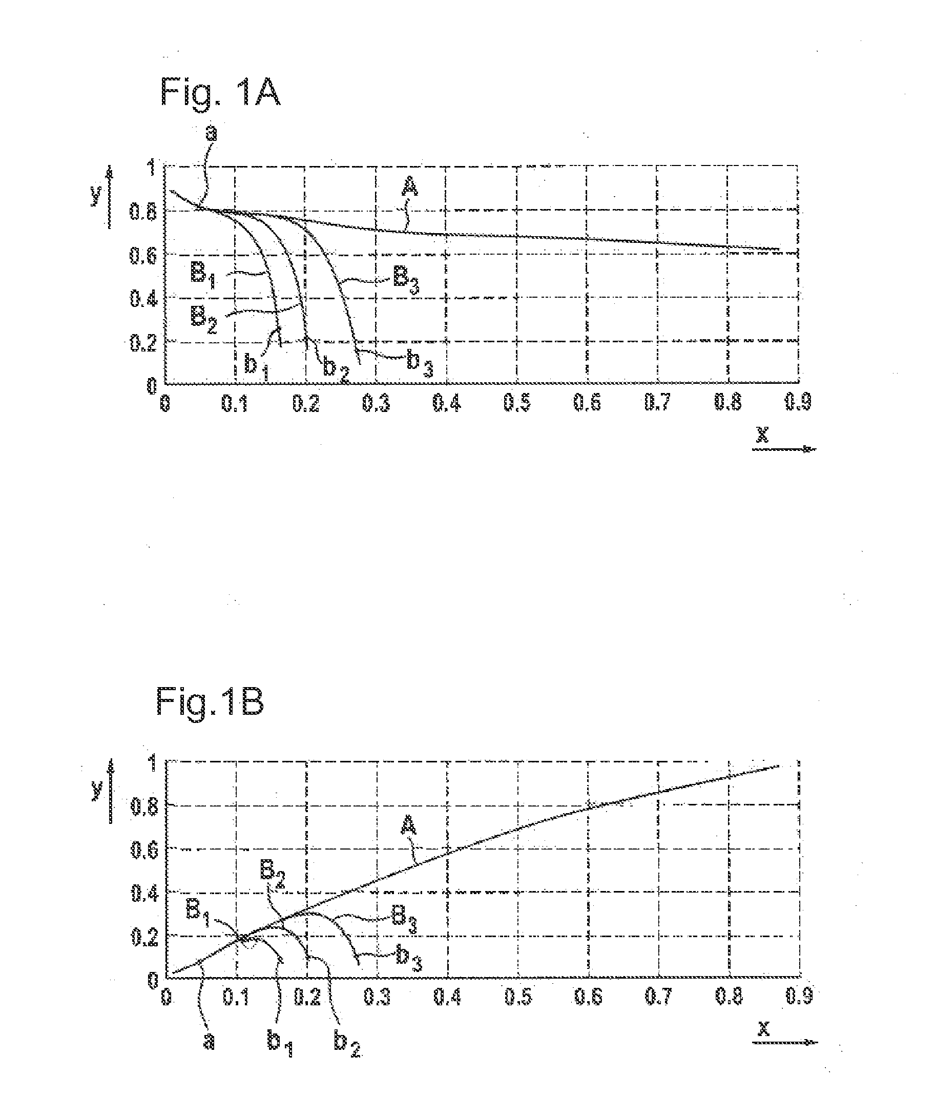
[0038]FIGS. 1A and 1B show graphs illustrating the ratio between the current density and the voltage and electrical power in a normal operating mode and in a depletion operating mode. In this case, FIG. 1A shows the ratio of the current density in A / cm2 (x axis) to the cell voltage in V (y axis), and FIG. 1B shows the ratio of the current density in A / cm2 (x axis) to the electrical power density in W / cm2 (y axis).

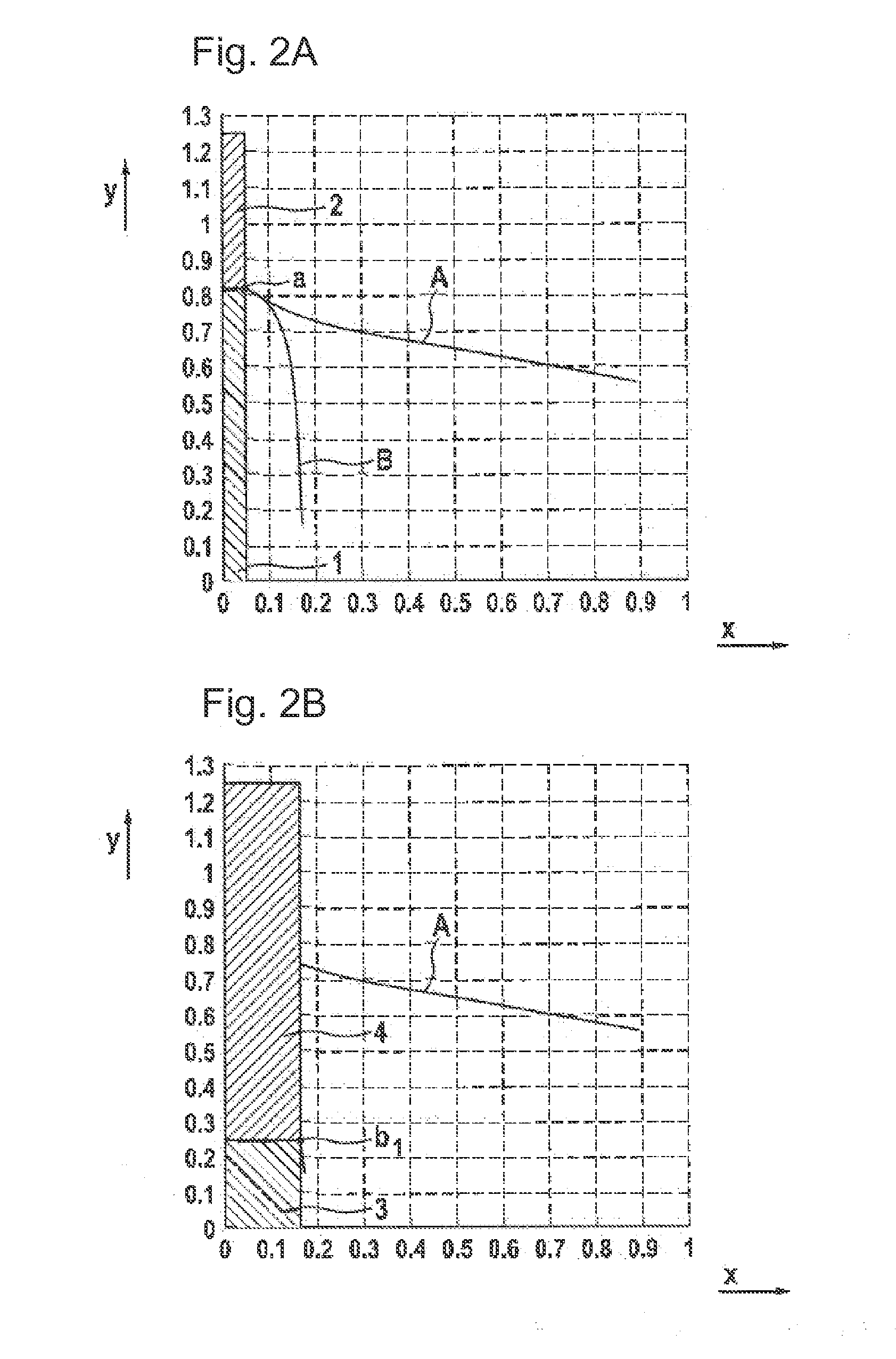
[0039]The graphs in FIGS. 1A and 1B firstly show the response of a fuel cell system when the fuel cell is always supplied to a sufficient extent with the reaction partners, i.e. with anode gas and cathode gas (lines A) and the response of the fuel cell in a cathode gas depletion operating mode (lines B).

[0040]In respect of a normal operating mode, it can be seen here from FIG. 1A that a defined cell voltage is set depending on electrical current. In this case, FIG. 1A shows the typical voltage profile of a fuel cell over current density. The more current is output by the fu...


PUM

PropertyMeasurementUnit
voltageaaaaaaaaaa
current consumptionaaaaaaaaaa
mass flowaaaaaaaaaa

Abstract

The present invention relates to a method for operating a fuel cell system, comprising the following method steps:a) conducting a defined quantity of anode gas to an anode and conducting a defined quantity of cathode gas to a cathode, wherein a defined voltage is set at a defined current consumption and a defined power provision, whereinb) in order to increase the waste heat of the fuel cell for a defined, temporally limited duration, the fuel cell is operated in a cathode gas depletion state.Such a method provides improved thermal control of the fuel cell even in the case of coldstarting or after operation in the partial load mode. The present invention also relates to a fuel cell system.

Description

BACKGROUND OF THE INVENTION[0001]The present invention relates to a method for operating a fuel cell and to a fuel cell system.[0002]Fuel cells are promising energy sources. For example, the fuel cell based on pure hydrogen as combustion gas provides advantages since pure water is produced as emission. Furthermore, fuel cells can provide improved efficiency primarily in the partial load range in comparison with internal combustion engines, which can become noticeable in the consumption of the vehicle. Thus, the consumption of a mid-range vehicle operated using a fuel cell can be, for example, when converted, 3 liters of gasoline per 100 kilometers.[0003]Owing to the good efficiency of fuel cells, the waste heat produced for example in the case of motor vehicles can under some circumstances only actually be sufficient for heating the driver's cab and / or keeping the fuel cell system warm, for example. In detail, under some circumstances in fuel cell systems which are operated over a r...

Claims


Application Information

Patent Timeline
Patent Type & Authority Applications(United States)
IPC IPC(8): H01M8/04
CPCH01M8/04701Y02E60/50H01M8/0491Y02T90/32H01M8/04268H01M8/04753H01M2250/20H01M8/04007Y02T90/40
Inventor GOTTWICK, ULRICHZIRKEL, DANIELHAWLICZEK, SEBASTIAN
Owner ROBERT BOSCH GMBH
Learn More