Method and Apparatus for Producing Composite Fillers

Active Publication Date: 2013-05-02
THE BOEING CO
View PDF4 Cites 36 Cited by
  • Summary
  • Abstract
  • Description
  • Claims
  • Application Information

AI Technical Summary

Benefits of technology

[0007]The disclosed embodiments provide a method and apparatus for producing a composite filler having improved toughness and strength, and which reduces the time and labor required to produce a filler having varying cross section along its length. Improved filler toughness and strength and achieved by laminating plies of fiber prepreg in which the laminated plies have varying fiber orientatio

Problems solved by technology

In some cases, there may be one or more gaps in areas of joints between the members that may reduce the strength of the joints.
For example, ply pad-ups, ply drop-offs and/or joggles on a composite skin may result in a variable gap between the skin and an overlying stiffener, such as a string

Method used


Image

  • Method and Apparatus for Producing Composite Fillers
  • Method and Apparatus for Producing Composite Fillers
  • Method and Apparatus for Producing Composite Fillers

Examples


Example

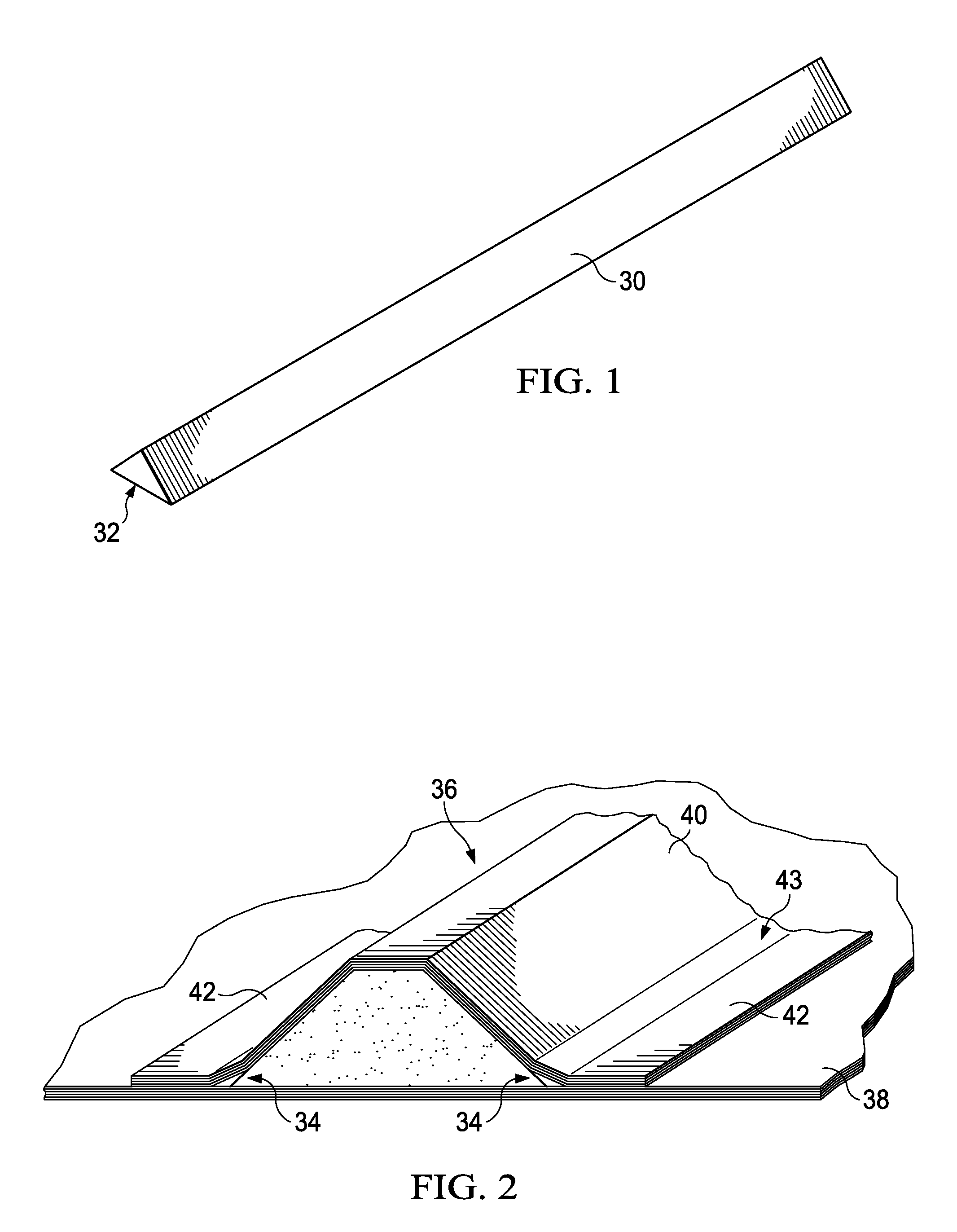
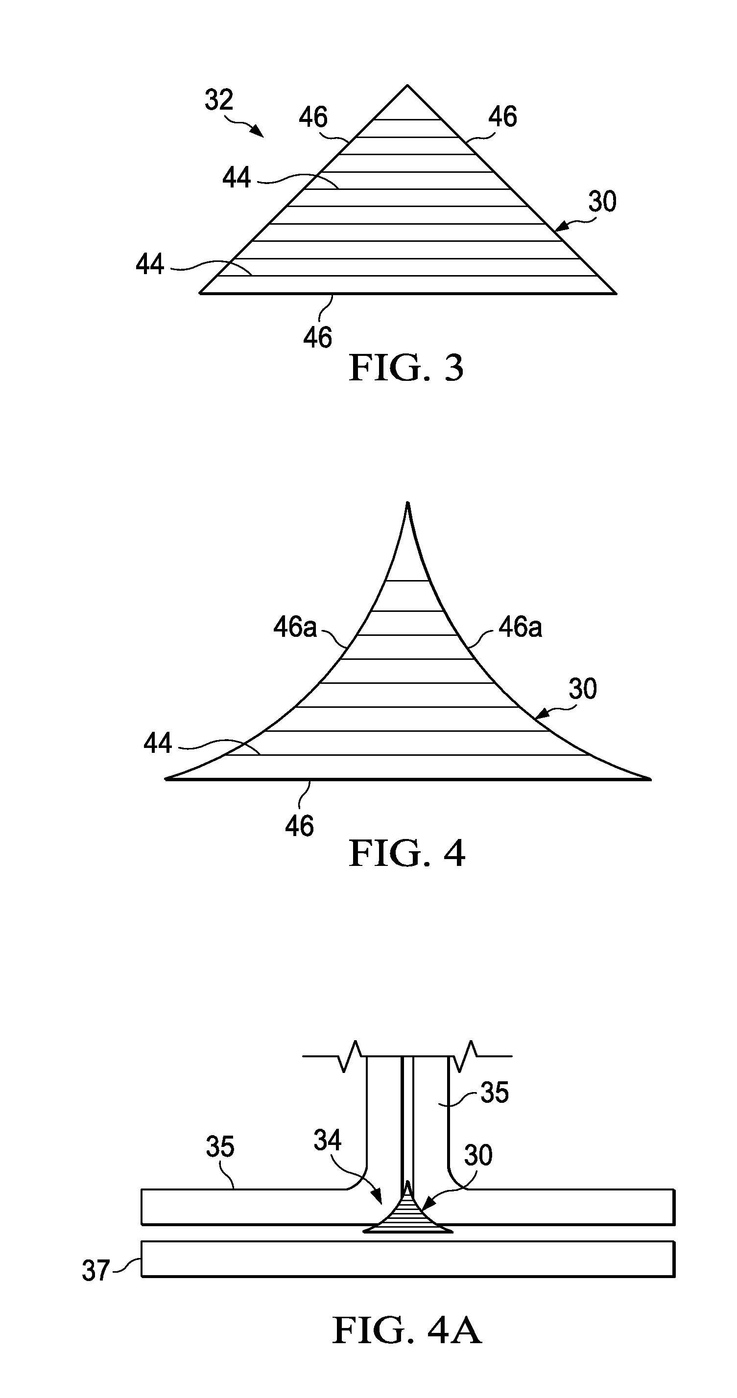
[0046]Referring first to FIGS. 1-3, the disclosed embodiments relate to a method and apparatus for producing a composite filler 30 suitable for filling gaps between composite members, such as, without limitation, a stringer 36 attached to a skin 38. The stringer 36 includes a hat section 40 joined to a pair of flanges 42 by a radius section 43 that results in gaps 34 that are generally triangular in cross sectional shape along the length of the stringer 36. In some applications, the cross section of the gaps 34 may vary along the length of the gap 34, either in its area or in its shape, or both. This variance may be caused, for example and without limitation, by ply drop-offs, pad-ups, or joggles (not shown) in the skin 38, and / or curvatures in either the stringer 36 or the skin 38. The stringer 36 and skin 38 are merely illustrative of a wide range of joined structural members having variable gaps that may require a filler 30 in order to improve structural performance.
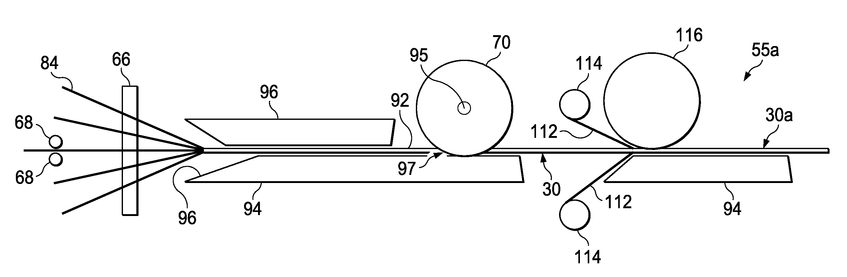
[0047]Referri...


PUM

PropertyMeasurementUnit
Temperatureaaaaaaaaaa
Lengthaaaaaaaaaa
Shapeaaaaaaaaaa

Abstract

Apparatus for producing a composite filler includes at least one die and a device for moving a stack of reinforced ply strips through the die. The die has peripheral die face adapted for forming the ply strip stack into a desired cross sectional shape. The cross section of the die face may vary around the periphery of the die.

Description

BACKGROUND INFORMATION[0001]1. Field:[0002]The present disclosure generally relates to the fabrication composite structures, and deals more particularly with a method and apparatus for producing fillers used to fill gaps in such structures.[0003]2. Background:[0004]Composite structures may be fabricated by joining two or more members together. In some cases, there may be one or more gaps in areas of joints between the members that may reduce the strength of the joints. In order to strengthen the joints, the gaps are filled with fillers, sometimes also referred to as radius fillers, fillets or noodles. The filler may be formed from composite materials such as adhesive, prepreg tape or fabric. In some cases, the cross section of the gap may vary in size and / or shape along its length as a result of the adjoining composite members converging or diverging from each other. For example, ply pad-ups, ply drop-offs and / or joggles on a composite skin may result in a variable gap between the s...

Claims


Application Information

Patent Timeline
IPC IPC(8): B32B38/04
CPCB29C70/52B29C70/526B29D99/0007B29L2031/003B29L2031/008B29D99/0005Y10T156/1023Y10T156/1031Y10T156/1044Y10T156/1075Y10T156/12Y10T156/125Y10T156/1317Y10T156/133Y10T156/14B32B37/0046B32B38/0004
Inventor ANDERSON, DONALD A.CHAPMAN, MICHAEL ROBERTKISCH, ROBERT A.ZABALLOS, KENNETH PAUL
Owner THE BOEING CO
Why Eureka
Try Eureka