Magnetic encoder with improved resolution

a technology of magnetic encoder and resolution, applied in the field of magnetic encoder, can solve the problems of large error, loss of synchronization, complicated correcting mechanism or circuit, etc., and achieve the effect of improving resolution and interpolation accuracy, and facilitating the generation of sinusoidal magnetic flux

Inactive Publication Date: 2013-05-02
SANYO DENKI CO LTD
View PDF0 Cites 11 Cited by
  • Summary
  • Abstract
  • Description
  • Claims
  • Application Information

AI Technical Summary

Benefits of technology

[0012]An object of the present invention is to provide a low-cost magnetic encoder that facil...

Problems solved by technology

In the magnetic encoders which use only magnets, however, an error due to the magnets is detected as it is, which may result in a large error.
However, the correcting mechanism or circuit may be complicated.
Therefore, synchronization may be lost upon abrupt rotation.
In addition, an error due to one magnet is detected as it is, which may result in a large error.
In an encoder used for speed measurement in a permanent-excitation electric synchronous machine disclosed in Japanese Patent Application Publication No. 2008-514906, a regular sinusoidal wave may not be obtained, and the accuracy may not be increased.
In addition, a large amount of magnetic flux leaks, and only a small amount of magnetic flux reaches a magnetic sensor portion.
Therefore, the S/N ratio may not be increased, which may result in a low accuracy.
However, distortion may still remain, and an accurate sinusoidal wave may not be obtained.
In a linear resolver disclosed in Japanese Patent Application Publication No. 2008-64537, it is difficult to make a calibration in case of a long stroke, and a small pitch may not be used.
Therefore, the accuracy may not be increas...

Method used


Image

  • Magnetic encoder with improved resolution
  • Magnetic encoder with improved resolution
  • Magnetic encoder with improved resolution

Examples


Embodiment Construction

[0046]Magnetic encoders according to a plurality of embodiments of the present invention will be described in detail below with reference to the drawings. In the drawings referenced in the following description, in order to clarify illustration, cross sections are not hatched excluding some exceptions.

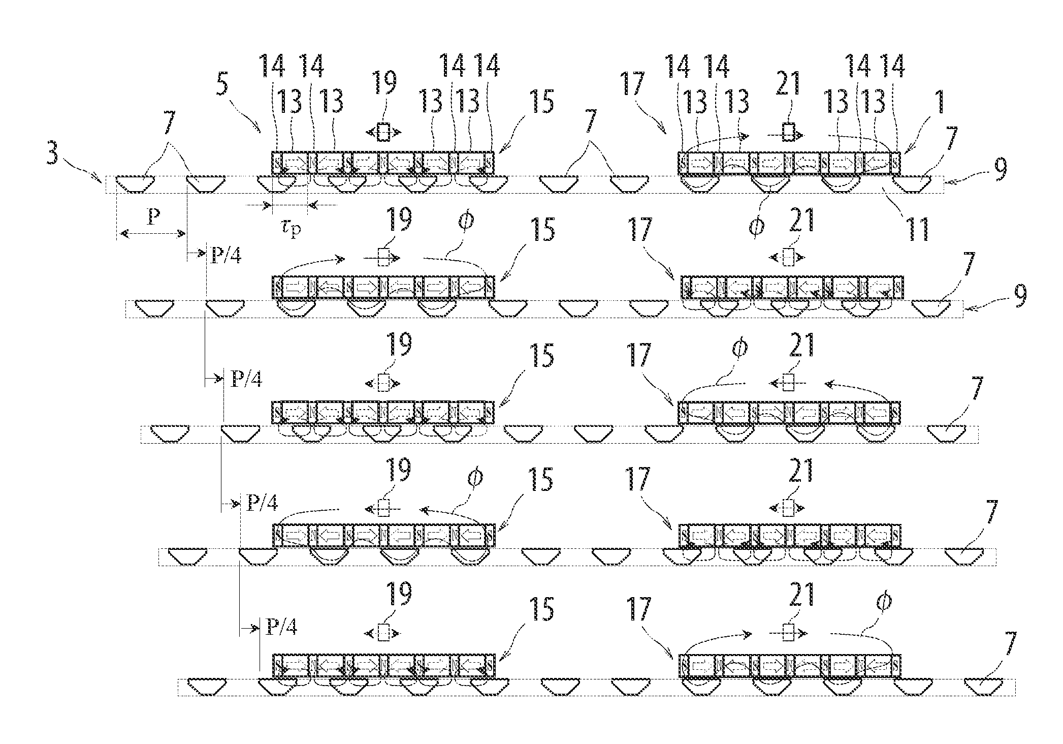
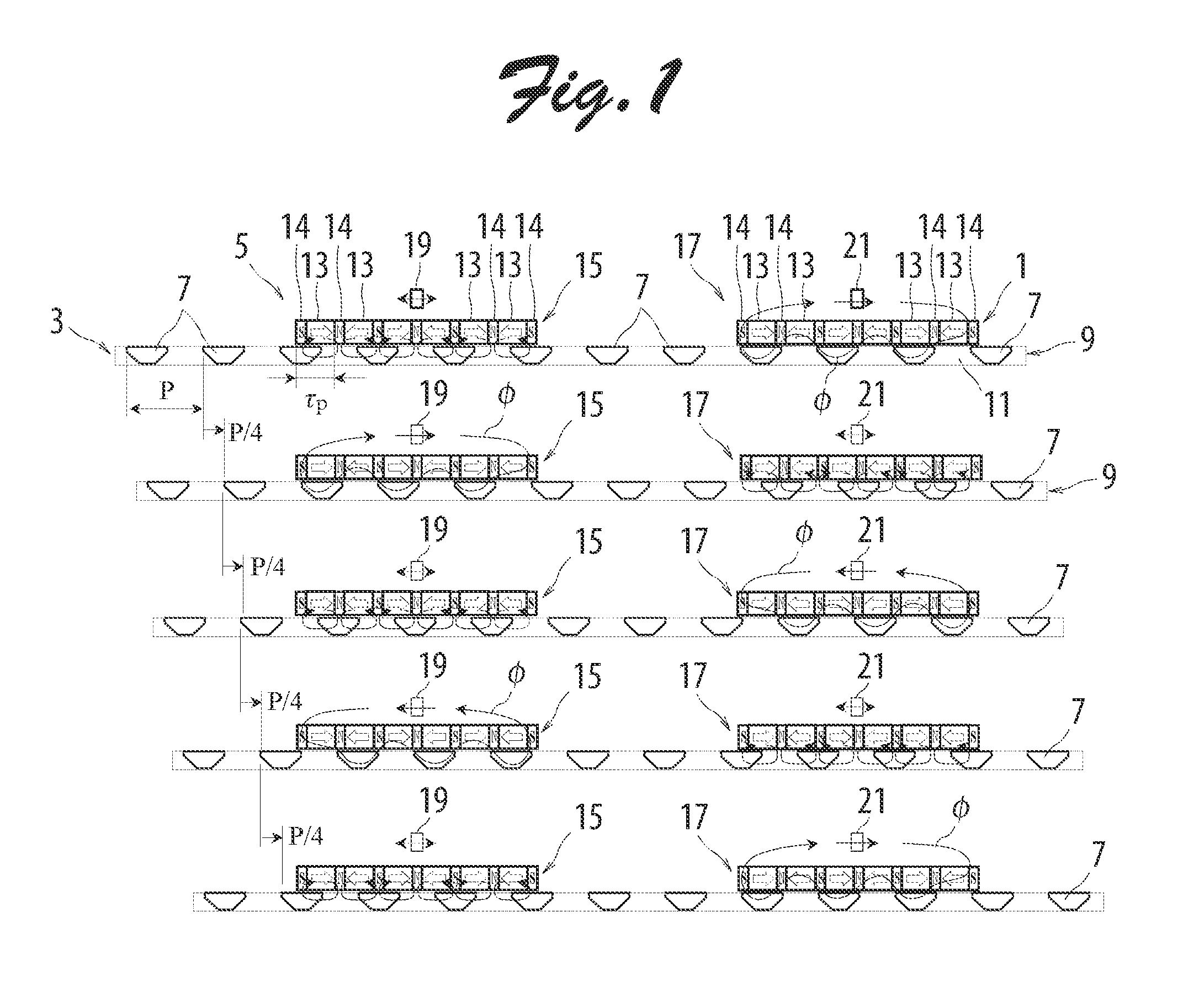
[0047]FIG. 1 illustrates operation of an embodiment in which a magnetic encoder according to the present invention is applied to a linear magnetic encoder. In FIG. 1 illustrates operation of the linear magnetic encoder according to the embodiment chronologically from top to bottom. As shown in FIG. 1, a linear magnetic encoder 1 includes a mover 3 and a stator 5, and generates a signal indicating the position of the mover 3 with respect to the stator 5. The mover 3 has an integral structure in which one magnetic piece array 9 formed from a plurality of magnetic pieces 7 is supported by a support member 11 formed from a non-magnetic member. The magnetic pieces 7 each have a vertical cro...


PUM


Abstract

A low-cost magnetic encoder that facilitates generating sinusoidal magnetic flux is provided. First and second permanent magnet arrays each include a plurality of permanent magnets arranged such that magnetic poles having the same polarity face each other, and magnetic yokes disposed on side surfaces of the plurality of permanent magnets. The permanent magnets and the magnetic yokes are arranged side by side at a predetermined pitch in the moving direction of a magnetic piece array. First and second magnetic detectors corresponding to the first and second permanent magnet arrays are disposed in a positional relationship allowing detection of leakage magnetic flux generated when the permanent magnet arrays and the magnetic piece array are displaced with respect to each other.

Description

TECHNICAL FIELD[0001]The present invention relates to a magnetic encoder.BACKGROUND ART[0002]Magnetic encoders including magnets and magnetic detecting elements are used. In the magnetic encoders which use only magnets, however, an error due to the magnets is detected as it is, which may result in a large error. In order to reduce such an error, magnetic encoders provided with a correcting mechanism are also proposed. However, the correcting mechanism or circuit may be complicated. For example, in a multi-rotation encoder disclosed in Japanese Patent No. 4258376, which utilizes magnetic coupling, the proportion of a magnetically coupled area is small, and the allowable transfer torque is low. Therefore, synchronization may be lost upon abrupt rotation. In addition, an error due to one magnet is detected as it is, which may result in a large error.[0003]In an encoder used for speed measurement in a permanent-excitation electric synchronous machine disclosed in Japanese Patent Applica...

Claims


Application Information

Patent Timeline
IPC IPC(8): G01B7/30
CPCG01D5/2451G01B7/30G01D5/244
Inventor SUGITA, SATOSHITANG, YUQIMISAWA, YASUSHI
Owner SANYO DENKI CO LTD
Why Eureka
Try Eureka