Mounting Mechanism

a technology of mounting mechanism and screw, which is applied in the direction of screw, load modification fastener, washer, etc., can solve the problems of insufficient life time and reliability, difficult to achieve, and high precision of drift tube mounting, so as to reduce the number of components, avoid connecting screw bending, and facilitate mounting

a technology of mounting mechanism and screw, which is applied in the direction of screw, load modification fastener, washer, etc., can solve the problems of insufficient life time and reliability, difficult to achieve, and high precision of drift tube mounting, so as to reduce the number of components, avoid connecting screw bending, and facilitate mounting

US20130108391A1Inactive Publication Date: 2013-05-02EUROPEAN ORGANIZATION FOR NUCLEAR RESEARCH

Image

  • Mounting Mechanism
  • Mounting Mechanism
  • Mounting Mechanism

Examples


Embodiment Construction

[0038]For the purposes of promoting an understanding of the principles of the invention, reference will now be made to the preferred embodiment illustrated in the drawings and specific language will be used to describe the same. It will nevertheless be understood that no limitation of the scope of the invention is thereby intended, such alterations and further modification in the illustrated device and such further applications of the principles of the invention as illustrated therein being contemplated as would normally occur now or in the future to one skilled in the art to which the invention relates.

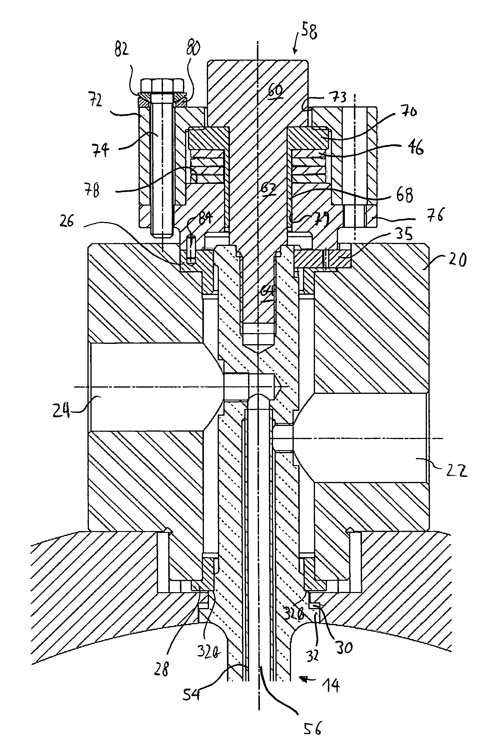
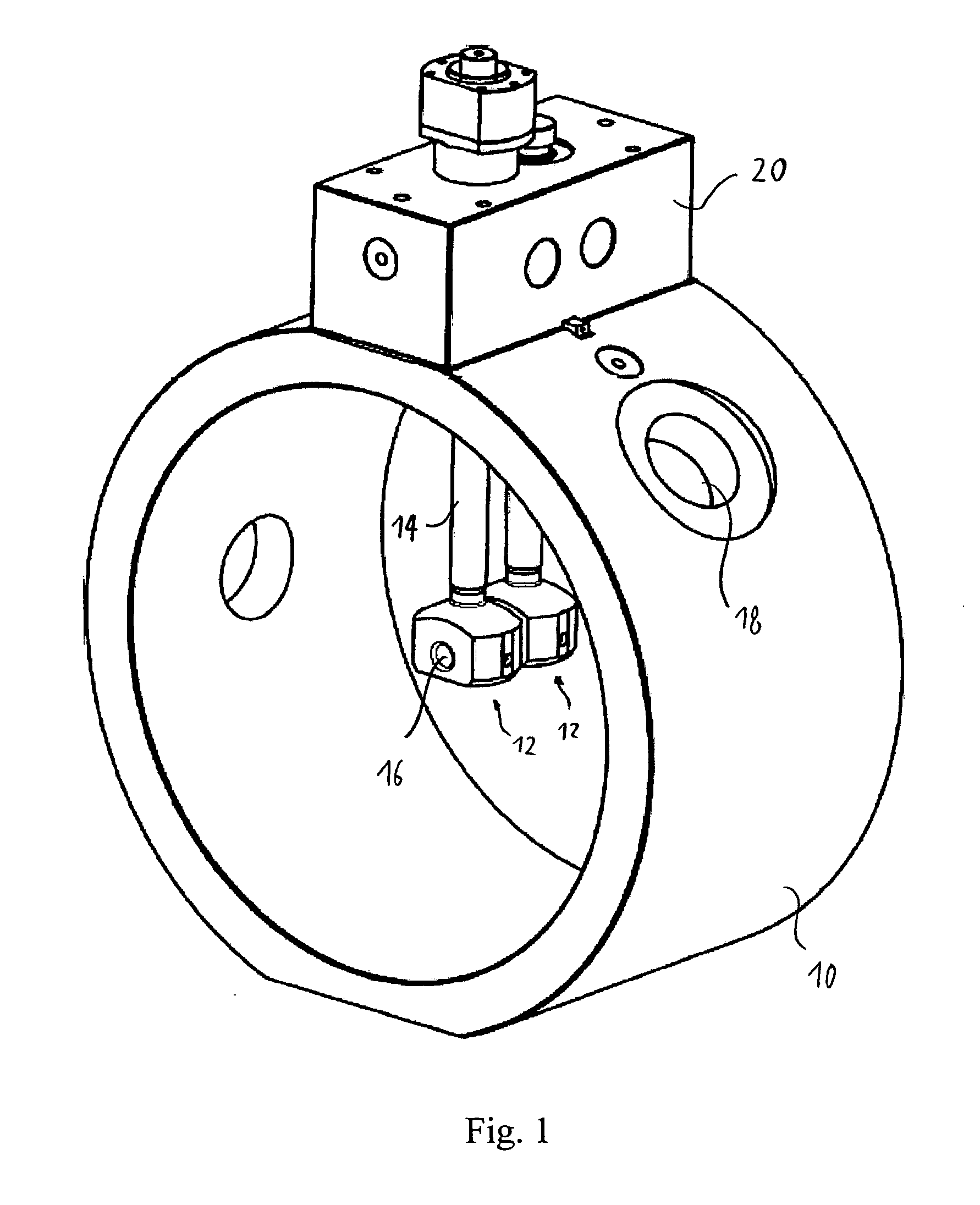
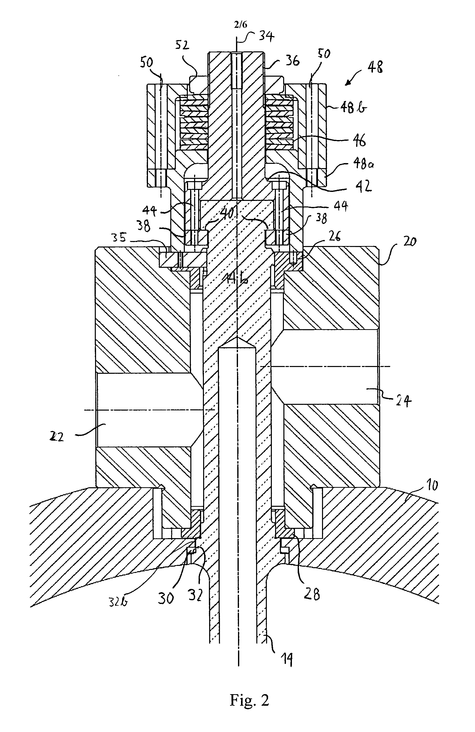
[0039]In FIG. 3, a perspective sectional view of a drift tube 12, a holding element 14, a girder 20 and the mounting mechanism according to a preferred embodiment of the invention is shown. Similar or identical components as compared to the prior art described with reference to FIGS. 1 and 2 will be designated with the same reference signs. A more detailed sectional view of the mount...


PUM


Abstract

Disclosed herein is a mounting mechanism such as a drift tube mounting mechanism for mounting a drift tube provided in a drift tube accelerator vessel 10 via an elongate holding element 14. The mounting mechanism comprises a biasing mechanism comprising one or more disc spring members 46 for axially biasing the elongate holding element 14 with respect to the vessel towards a mounting position. The mounting mechanism further comprises a screw 58 having a head portion 60 and a shaft portion, said shaft portion comprising a threaded portion 64 for screwing into the elongate holding element 14. The mounting mechanism further comprises a bushing 66 comprising a sleeve portion 68 receiving at least a part of the screw shaft and separating the one or more disc spring members 46 from said screw shaft portion. The screw head portion 60 is configured to receive the axial biasing force generated by the one or more disc spring members 46.

Description

FIELD OF THE INVENTION[0001]The present invention relates to amounting mechanism for mounting an elongate element on a structure. In a particular embodiment, the invention relates to a mechanism for mounting a drift tube in a drift tube accelerator via an elongate holding element.PRIOR ART[0002]A prior art mounting mechanism related to the present invention has been developed by the applicant for use in drift tube accelerators. Drift tube linear accelerators for accelerating charged particles such as protons are known in the field. In FIG. 1, a mockup of a prior art drift tube accelerator is shown in a perspective view. As is seen in FIG. 1, a drift tube accelerator comprises an elongate cylindrical vessel, of which only a virtual slice is shown for illustration purposes in FIG. 1. Along the longitudinal axis of the vessel 10, a plurality of drift tubes 12 are disposed (only two of which are shown in the slice of FIG. 1), which are mounted via elongate holding elements 14 at a first...

Claims


Application Information

Patent Timeline
02 May 2013
Publication
US20130108391A1
IPC
F16B31/04; F16B43/00
CPC
F16B5/0266; F16B31/04; F16B43/00; H05H7/22; F16B43/02
Inventors
RAMBERGER, SUITBERT; BOURQUIN, PIERRE