Auxiliary amalgam for a low pressure discharge lamp
- Summary
- Abstract
- Description
- Claims
- Application Information
AI Technical Summary
Benefits of technology
Problems solved by technology
Method used
Image
Examples
example i
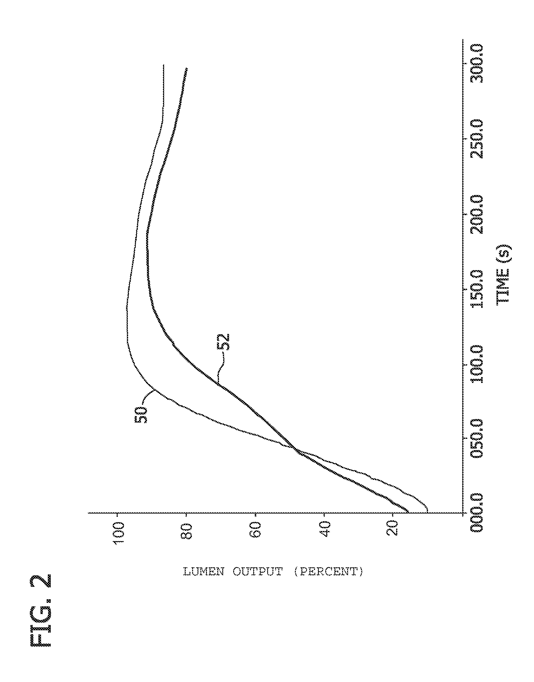
[0034]A comparative example test comparing the lumen run-up time characteristics of an exemplary sample discharge lamp of an embodiment of the invention designated Sample A, and a control sample discharge lamp designated Sample B. Sample A is a discharge lamp having an auxiliary amalgam-forming material integrated into the lamp's phosphor layer as described above. Sample B is a similar discharge lamp which only had a conventional amalgam pellet positioned in the envelope of the lamp.
[0035]The phosphor layer of Sample A was formed by blending 30 mg (milligrams) of indium powder (average size of about 40 micrometers) with 100 g (grams) of a phosphor blend that includes phosphor particles of red, green and blue emitting phosphors. A portion of this mixture / blend was coated onto the lamp envelope of Sample A in a conventional manner as described above. The Sample A discharge lamp was dosed with 0.8 mg of Hg added as a conventional amalgam pellet. The phosphor layer of Sample B discharge...
example ii
[0037]A comparative example test comparing the lumen run-up time characteristics of an exemplary sample discharge lamp of an embodiment of the invention designated Sample C, and a control sample discharge lamp designated Sample D. Sample C is similar to Sample A and also includes an auxiliary amalgam integrated into the lamp's phosphor layer as described above. Sample D is similar to Sample B discharge lamp but which additionally includes an amalgam flag welded onto the mount stem in the envelope of the lamp.
[0038]The phosphor layer of Sample C was formed by blending 30 mg (milligrams) of indium powder (average size of about 40 micrometers) with 100 g (grams) of a phosphor blend that includes phosphor particles of red, green and blue emitting phosphors. A portion of this mixture / blend was coated onto the lamp envelope of Sample A in a conventional manner as described above. The Sample C discharge lamp was dosed with 0.8 mg of Hg added as a conventional amalgam pellet. The phosphor l...
example iii
[0040]In this Example, 20 Watt, T3 helical compact fluorescent lamps were constructed comprising varying amounts of amalgam-forming material integrated in a standard triphosphor layer, in accordance with aspects of this disclosure. The following values were employed for Indium powder per 100 g of phosphor in the phosphor composition: 0 (i.e., prior art), 5, 10, 20, 30, 40 and 50 mg of Indium powder. Each lamp also comprised a standard Hg amalgam pellet to provide up to 1.0 mg of Hg in the lamp. Five to 6 lamps per value of content of amalgam-forming material were constructed and tested, to determine the mean time (in seconds) needed to attain a lumen value of 80% of stabilized lumen output. In this example, the time needed to attain 80% of stabilized lumen output, is referred to as the lumen run-up time. FIG. 3 shows the values for mean lumen run-up time (in seconds) as a function of content of amalgam-forming material in the phosphor layer, expressed as mg per 100 g of phosphor in ...
PUM
 Abstract
Description
Claims
Application Information
 - R&D
- Intellectual Property
- Life Sciences
- Materials
- Tech Scout
- Unparalleled Data Quality
- Higher Quality Content
- 60% Fewer Hallucinations
Browse by: Latest US Patents, China's latest patents, Technical Efficacy Thesaurus, Application Domain, Technology Topic, Popular Technical Reports.
© 2025 PatSnap. All rights reserved.Legal|Privacy policy|Modern Slavery Act Transparency Statement|Sitemap|About US| Contact US: help@patsnap.com


