Aortic Occlusion Catheter

a catheter and aortic occlusion technology, applied in the field of aortic occlusion catheters and catheters, can solve the problems of significant complications, significant increase in mortality and morbidity for reoperation, and weeks of hospitalization and months of recuperation time, and achieve the effect of sufficient length and flexibility

Inactive Publication Date: 2013-05-09
EDWARDS LIFESCIENCES CORP
View PDF8 Cites 11 Cited by
  • Summary
  • Abstract
  • Description
  • Claims
  • Application Information

AI Technical Summary

Benefits of technology

[0008]In at least some embodiments, an antegrade cardioplegia delivery catheter is described. An example antegrade cardioplegia delivery catheter may be advanced into an aorta of a patient's heart for antegrade delivery of a fluid. Exemplary delivery catheters may include an elongated shaft having a proximal end and a distal end, with the elongated shaft having sufficient length and flexibility so that the proximal end may extend intraluminally through a patient's femoral or other artery when the distal end is positioned in the aorta of a patient. The elongated shaft can include multiple lumens, including at least a primary lumen configured to receive antegrade cardioplegia. One or more secondary lumens may also be included and can be provided for expanding an expandable member, measuring a pressure (e.g., aortic root pressure) in the heart of the patient, or passing a core element along all or a portion of the length of the elongated shaft. The core element may be configured to define a predetermined shape that causes the elongated shaft to flex to a conforming shape that approximates a curvature of a lower or bottom surface of the patient's aortic arch.
[0009]In some embodiments, a

Problems solved by technology

However, such surgery often entails weeks of hospitalization and months of recuperation time, in addition to the pain and trauma suffered by the patient.
Moreover, while the average mortality rate associated with this type of procedure is about two to fifteen percent for first-time surgery, mortality and morbidity are sign

Method used


Image

  • Aortic Occlusion Catheter
  • Aortic Occlusion Catheter
  • Aortic Occlusion Catheter

Examples


Embodiment Construction

[0026]Exemplary embodiments of the present disclosure are directed to accessing a body lumen in order to perform a medical or other procedure. For instance, during a minimally invasive surgical procedure, a surgeon may access a body lumen such as the femoral artery or jugular, and extend one or more elements through the vasculature of the patient so as to access a location remote from the access site. Devices that may be extended through the access site and to a remote location of the surgical procedure include catheters, stents, guidewires, other surgical devices, or any combination of the foregoing. Thus, a variety of surgical procedures may be performed within the cavities of the body, particularly including minimally invasive and less invasive surgical procedures in which surgical instruments are introduced through an access site, and thereafter extended through body lumens to a desired location.

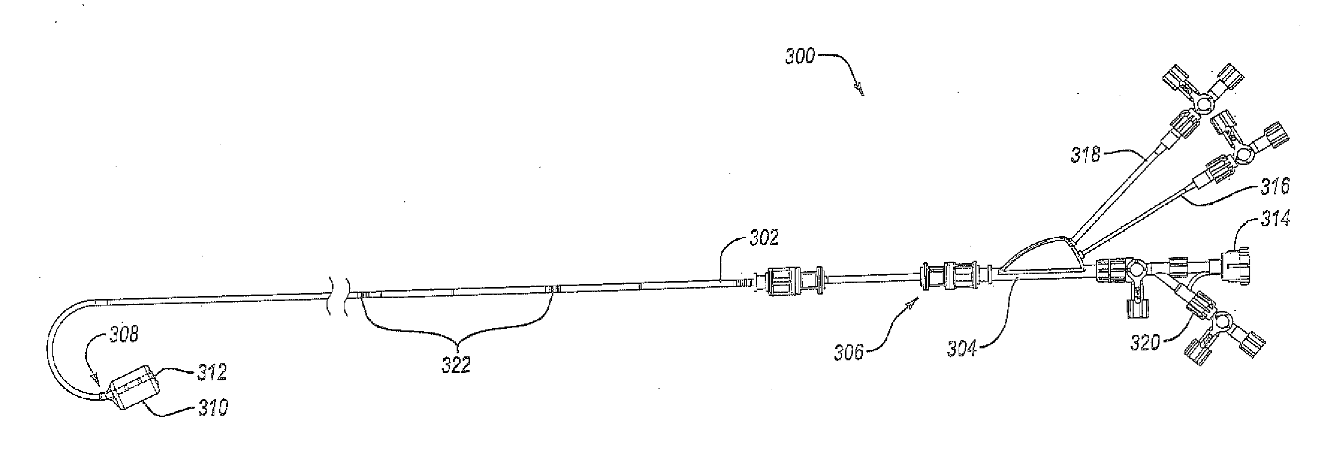
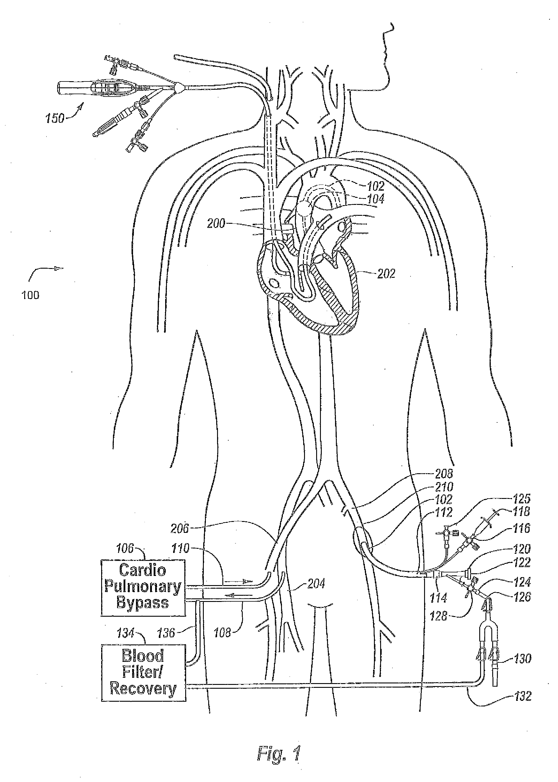
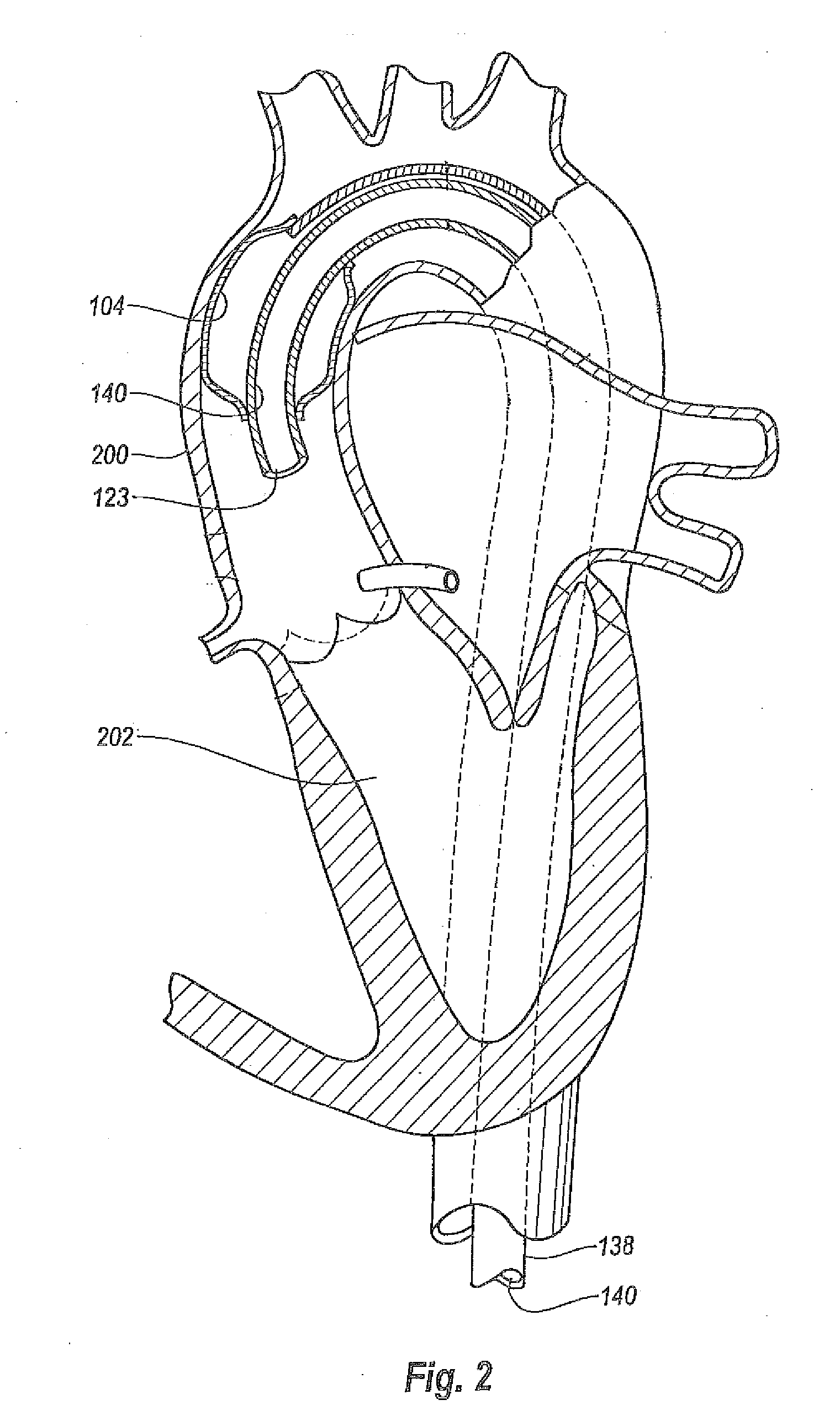
[0027]Reference is made to FIG. 1, which schematically illustrates an overall cardia...


PUM


Abstract

An cardioplegic fluid delivery catheter includes an expandable member for occluding the ascending aorta of a patient. A length of the catheter allows the distal end to be within the ascending aorta while the proximal end extends from a peripheral artery. The delivery catheter has a multi-lumen construction with a primary lumen extending configured to allow a cardioplegic fluid to be delivered to the aorta. Secondary lumens provide for balloon inflation and aortic root pressure monitoring. The delivery catheter includes a shaft having a pre-determined curve profile at a distal end of the delivery catheter. The pre-determined curve profile generally corresponds to the curve of the bottom surface of the aortic arch. The shaft may be eccentric to the expandable member such that retraction of the shaft causes a distal tip to be parallel within the ascending aorta.

Description

BACKGROUND[0001]1. Field of the Invention[0002]This invention relates generally to devices and techniques for performing cardiac procedures and particularly to catheter systems and methods for inducing cardioplegic arrest to facilitate the performance of cardiac procedures.[0003]2. The Related Technology[0004]Known techniques for performing major surgeries such as coronary artery bypass grafting and heart valve repair and replacement have generally required open access to the thoracic cavity through a large open wound, known as a thoracotomy. Typically, the sternum is cut longitudinally (i.e., a median sternotomy), providing access between opposing halves of the anterior portion of the rib cage to the heart and other thoracic vessels and organs. An alternate method of entering the chest is via a lateral thoracotomy, in which an incision, typically 10 cm to 20 cm in length, is made between two ribs. A portion of one or more ribs may be permanently removed to optimize access.[0005]In ...

Claims


Application Information

Patent Timeline
IPC IPC(8): A61M25/10
CPCA61M25/0032A61M25/0041A61M2025/1052A61M2025/0003A61M25/1002F04C2270/0421
Inventor DEHDASHTIAN, MARKJIMENEZ, JR., TEODORO S.HAYES, RBLARSEN, AMANDASCHULTING, EDWINBOUDEWIJN, LEX
Owner EDWARDS LIFESCIENCES CORP
Why Eureka
Try Eureka