Optimization of tank venting of a fuel tank

Inactive Publication Date: 2013-05-16
ROBERT BOSCH GMBH
View PDF26 Cites 7 Cited by
  • Summary
  • Abstract
  • Description
  • Claims
  • Application Information

AI Technical Summary

Benefits of technology

[0003]There may therefore be a need for an improvement in the tank venting strat

Problems solved by technology

In general, it is only possible to generate a vacuum in the intake pipe when the engine is running, and it is therefore impossible to regenerate the activated carbon filter when the engine is stationary.
Given increasingly smaller engines with turbocharging (downsizing), the vacuum in the intake pipe is furthermore no longer ade

Method used


Image

  • Optimization of tank venting of a fuel tank
  • Optimization of tank venting of a fuel tank

Examples


Embodiment Construction

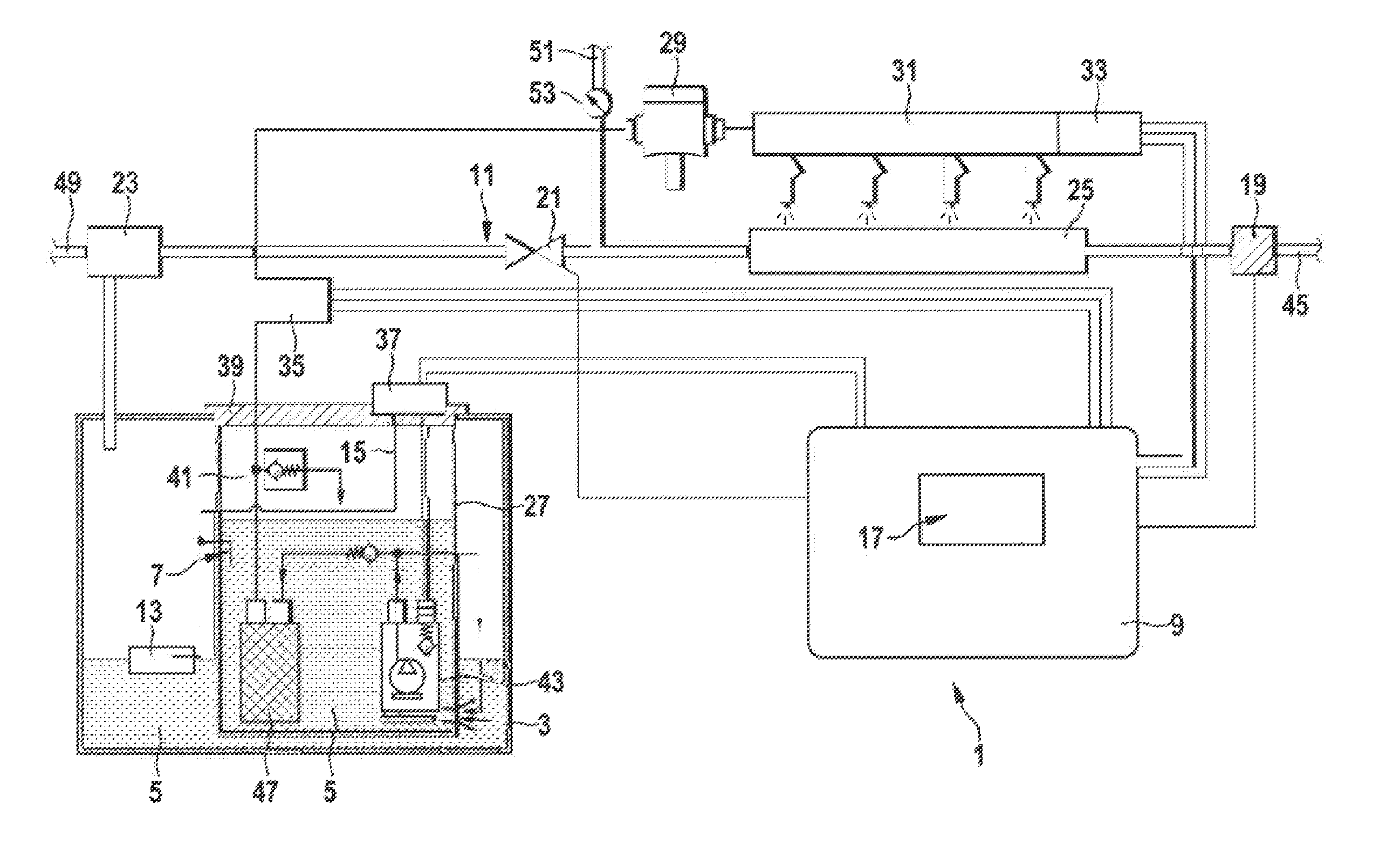
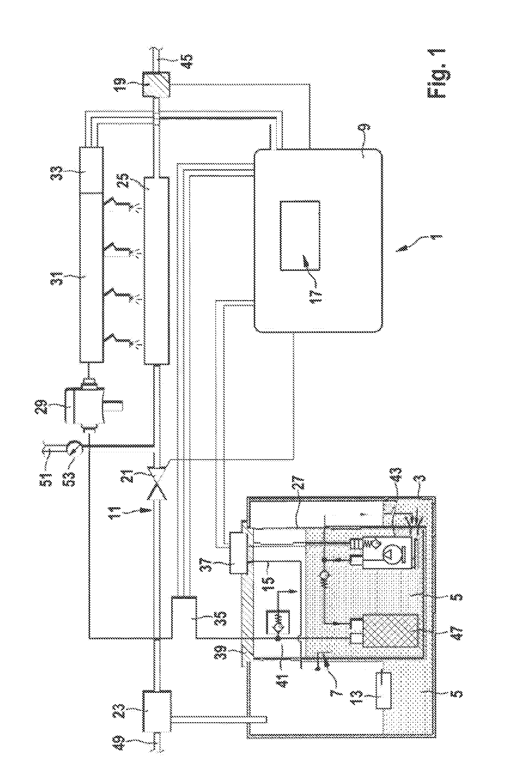
[0027]The FIGURE is only a schematic representation of the device according to the invention and of the components thereof in accordance with one embodiment of the invention. Spacings and size relationships, in particular, are not reproduced to scale in the FIGURE.

[0028]A high assumed loading of an activated carbon filter 23 of a motor vehicle must be reduced by tank venting phases. In the case of hybrid vehicles, tank venting can lead to forced switching on of the internal combustion engine 25. The system 1 illustrated in FIG. 1 optimizes tank venting in such a way that, for example, fewer instances of forced switching on of the internal combustion engine 25 are necessary or the controlled increase in the duty factor of the tank venting valve 21 can be performed more quickly.

[0029]The system 1 shown in FIG. 1 provides for the outgassing of the fuel 5 contained in the fuel tank 3 to be modeled. In the process, the system 1 uses a current fuel temperature determined by a temperature ...


PUM


Abstract

A system (1) for optimizing tank venting of a fuel tank (3) is presented. The system (1) has a temperature sensor (7), a closed-loop control unit (9) and a tank venting unit (11). The temperature sensor (7) is arranged directly in the fuel tank (3) and is designed to determine a current fuel temperature of a fuel (5) present in the fuel tank (3). The closed-loop control unit (9) is connected to the temperature sensor (7) and to the tank venting unit (11) and is designed to read out the current fuel temperature from the temperature sensor (7). The closed-loop control unit (9) is furthermore designed to control the tank venting unit (11) in accordance with the loading of the activated carbon filter, which in turn depends on the time profile of the fuel temperature.

Description

BACKGROUND OF THE INVENTION[0001]Exhaust gas reduction and monitoring are important concerns of modern branches of industry. Among the tasks required in the vehicle industry is the interception of fuel vapors from the fuel tank before they reach the environment. This is accomplished, for example, by means of an activated carbon filter (ACF), which can absorb highly volatile hydrocarbons.[0002]The activated carbon filter can be regenerated by being purged with fresh air, thus maintaining its absorption capacity. Regeneration can be accomplished, for example, by sucking fresh air from the environment through the activated carbon filter. For this purpose, there must, for example, be a vacuum in an intake pipe, and a tank venting valve (TVV) must be open. In general, it is only possible to generate a vacuum in the intake pipe when the engine is running, and it is therefore impossible to regenerate the activated carbon filter when the engine is stationary. Given increasingly smaller engi...

Claims


Application Information

Patent Timeline
IPC IPC(8): B60K15/035F02M33/02
CPCB60K15/035F02M33/02B60K2015/0358B60K2015/03561
Inventor GUTSCHER, ANDREASPOSSELT, ANDREASLORENZ, MARKO
Owner ROBERT BOSCH GMBH
Why Eureka
Try Eureka