Device for varying blade pitch of a lift rotor

a technology of lift rotor and blade pitch, which is applied in the direction of propellers, propulsive elements, water-acting propulsive elements, etc., can solve the problems of large noise and vibration of rotary wing aircraft in flight, source of noise and vibration, and high levels of vibration generated by the main rotor, so as to optimize increase the performance of the aircraft, and avoid use or even penalization

Active Publication Date: 2013-05-16
EUROCOPTER
View PDF8 Cites 38 Cited by
  • Summary
  • Abstract
  • Description
  • Claims
  • Application Information

AI Technical Summary

Benefits of technology

[0070]Firstly, it can be understood that using one or more flaps on each blade in order to control the pitch of the blades serves to reduce the force required for imparting cyclic control. The hydraulic actuators conventionally used for controlling the movements and the angle of inclination of the swashplate can then be replaced by actuators that develop just enough force, and in particular electric actuators.
[0125]Consequently, the use of an electric motor driving rotation of the tail rotor may be an advantageous solution for achieving an improvement in the performance of the aircraft.

Problems solved by technology

Furthermore, a rotary wing aircraft in flight generates a large amount of noise and vibration, in particular as a result of rotation of the blades and the main rotor assembly.
For example, while the aircraft is descending, the turbulence generated by the end of a blade lies on the path of the following blade, with which it comes into collision accompanied by a characteristic slapping sound, constituting a source of noise and vibration.
Furthermore, high levels of vibration can also be generated by the main rotor if an unbalance appears in the rotor.
In general, unbalance appears on a rotating element when the center of gravity of that element is not positioned on its axis of rotation.
Although that device is effective and in widespread use, it requires considerable forces in order to maneuver the blades, particularly on heavy aircraft.
Furthermore, the presence of a swashplate penalizes the performance of the aircraft because of its large weight and dimensions that are needed as a result of the large forces to be transmitted to the blades, thereby giving rise in particular to aerodynamic disturbances that lead to an increase in drag.
That makes it difficult to incorporate an actuator such as an electric motor or a hydraulic actuator in a blade together with its control system for modifying the angle of inclination of a flap positioned at the trailing edge of each of the blades.
It is also difficult to power such actuators, whether electrically or hydraulically, since power needs to pass from the stationary frame of reference to the rotary frame of reference, and that power must be sufficient for turning the flaps.
Solutions do indeed exist for transferring such power, e.g. slip rings, however the reliability of such systems in an environment having high levels of vibration cannot always be guaranteed.
Consequently, when using trailing edge flaps for primary flight control, such control circuit multiplication (i.e. duplication multiplication by a number greater than two) adds additional complexity in the configuration of actuators inside the blades and in the transfer of power from the stationary frame of reference to the rotary frame of reference, as mentioned above.
Even if that operation takes place quickly, e.g. in less than one second, there nevertheless exists a moment during which the aircraft is not properly controlled, since the system is not operational.
In contrast, if the swashplate is eliminated and replaced by actuators incorporated in the blades, i.e. in the rotary frame of reference, it is difficult to ensure that the flaps and consequently the blades remain synchronized over a cycle while the system is not operational.
Under such circumstances, an unbalance may appear in the main rotor due to the lack of synchronization of the blades.
The behavior of the aircraft can become unstable and very uncomfortable until the system has corrected the fault or the malfunction.
Any offset in this position of the center of gravity of the blade and consequently any offset in the center of gravity of the main rotor including the blade affects both the operation of the blade and the comfort of the aircraft, considerable amounts of unbalance and vibration potentially being generated in the main rotor.
Because of this, integrating actuators in blades adds elements that need to be taken into account when balancing a blade, and in particular the movement of the centers of gravity of actuators while they are in use potentially complicates such balancing, or even modifies balancing during a flight.
Although hydraulic technology has been in use for a long time and is well mastered, it nevertheless gives rise to certain constraints.
The elements needed for these functions, such as actuators and pumps are expensive and very penalizing in terms of weight.
Incorporating them often requires a large amount of flexible pipework and various ducts for feeding the various elements, thus adding weight, cost, and complexity for configuration in a volume that is limited.
Furthermore, the sealing of the various hydraulic elements needs to be very thorough in an environment where there is a high level of vibration, since any reduction or loss of hydraulic pressure gives rise to a degradation or even to a loss of the flight controls of the aircraft.
Hydraulic technology thus imposes constraints in terms of maintenance, and thus once more contributes to high costs in order to ensure reliability for the pumps, the actuators, and the hydraulic equipment as a whole.
Hydraulic technology, in particular in terms of the recyclability of its components, and its fluids in particular, can have a negative impact on the environment.

Method used


Image

  • Device for varying blade pitch of a lift rotor
  • Device for varying blade pitch of a lift rotor
  • Device for varying blade pitch of a lift rotor

Examples


first embodiment

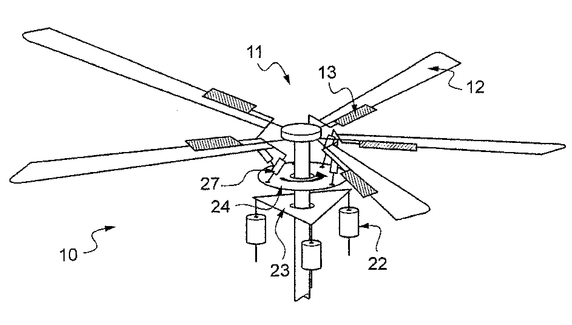
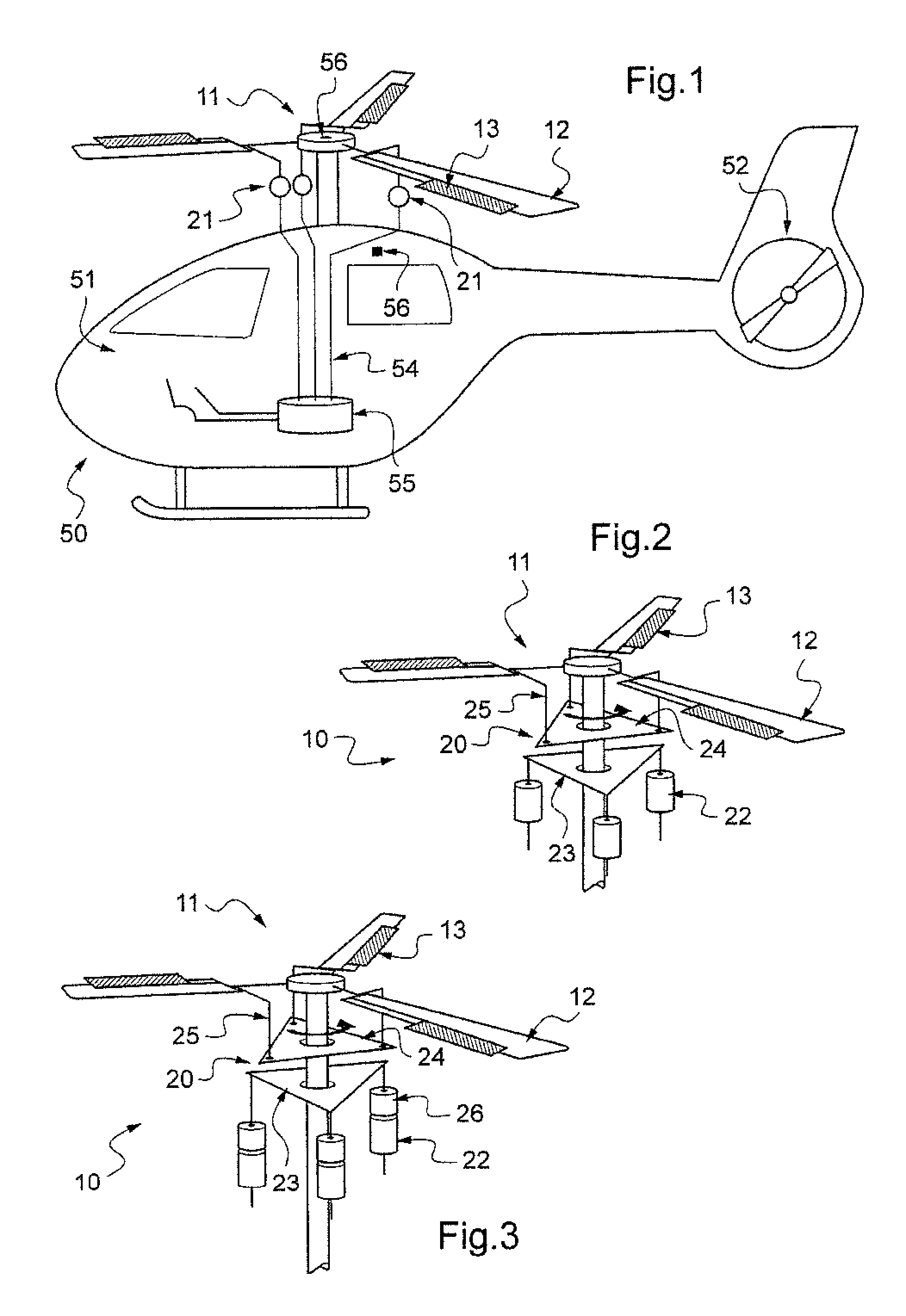
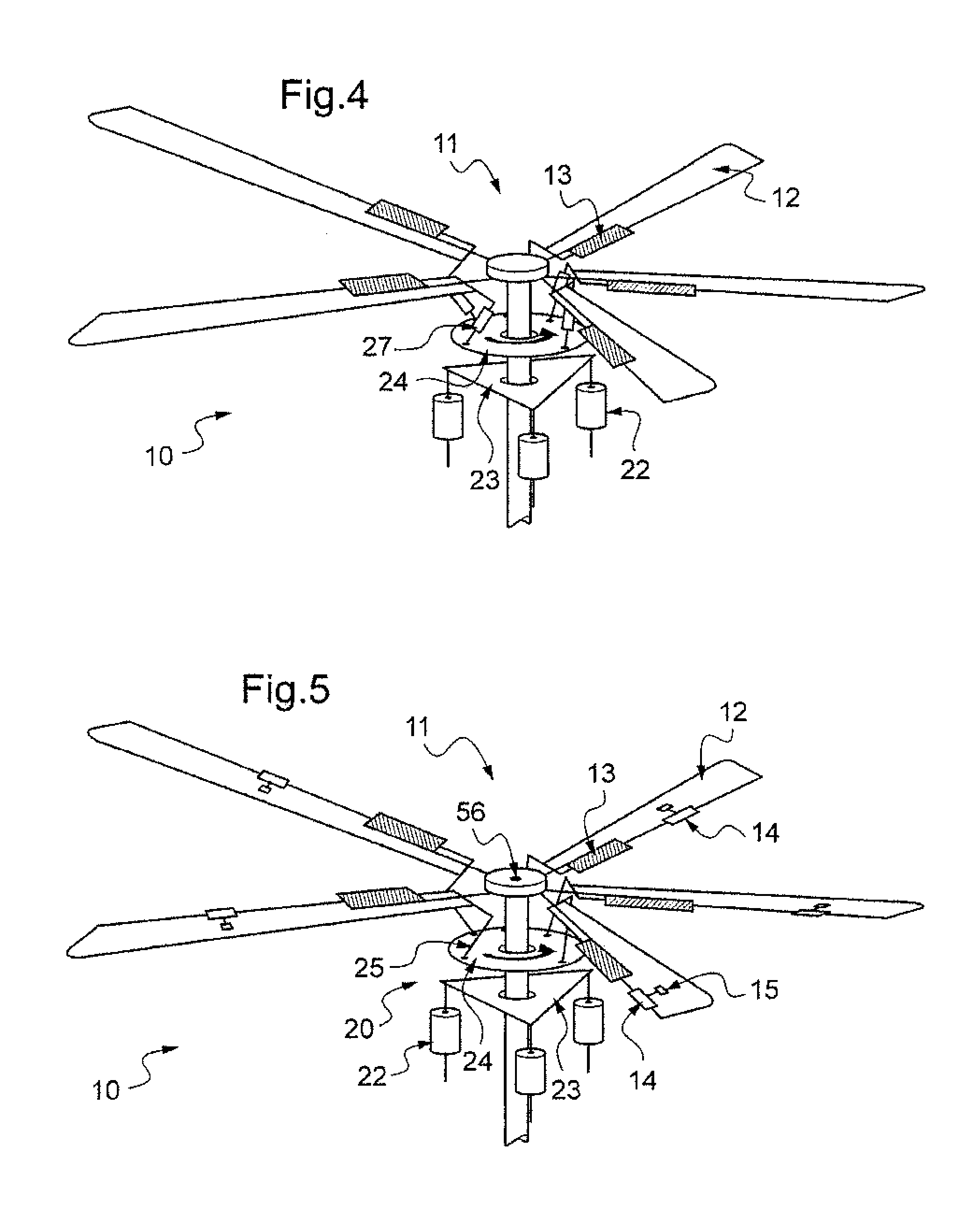
[0135]In a first embodiment shown in FIG. 2, the device 10 for varying blade pitch comprises a swashplate 20 having a non-rotating plate 23 and a rotating plate 24 that rotates with the main rotor 11. The rotating plate 24 acts via a mechanical connection 25 to drive the angle of inclination of each main flap 13 and consequently to vary the pitch of each blade 12. The main actuators 21 are electric actuators 22 located in a stationary frame of reference. These electric actuators 22 serve to move and vary the angle of inclination of the non-rotary plate 23, thereby controlling the main flaps 13 and consequently each corresponding blade 12, at least cyclically.

[0136]The movement of the non-rotary blade 23 gives rise to movement of the rotary plate 24 that acts via the mechanical connection 25 to cause each main flap 13 to vary its angle of inclination in identical manner, thereby varying the pitch of each blade 12. This performs collective variation of the pitch of the blades 12.

[0137...

second embodiment

[0138]In the invention specific to rotary wing aircraft 50 in which the main rotor 11 has three or four blades 12, the electric actuators 22 located in the stationary frame of reference have an operating frequency that enables the main flaps 13, and consequently the pitch of the blades 12, to be operated cyclically and multi-cyclically.

[0139]It should be observed that it is known that the noise and vibration generated in particular by the main rotor 11 can be attenuated by modifying the pitch of the blades 12 several times in a single revolution of the main rotor 11, with the pitch of the blades then being said to be controlled multi-cyclically.

[0140]Tests have also confirmed that these variations in blade pitch need to be performed at particular frequencies equivalent to 2ω, where ω corresponds to the speed of rotation of the main rotor 11, and also at (b−1)ω, bω, and (b+1)ω, where b corresponds to the number of blades 12 in the main rotor 11.

[0141]Thus, for the general case of a m...


PUM


Abstract

The present invention relates to a device (10) for varying blade pitch of a rotary wing aircraft (50) having a main rotor (11) with a plurality of blades (12), each blade (12) including at least one main flap (13) fastened to the trailing edge of the blade (12). The angle of inclination of each flap (13) is controlled via a swashplate (20). The device (10) makes provision for electric actuators controlled by a flight control system (54) to be mounted in a stationary frame of reference for the purpose of moving and varying the angle of inclination of the non-rotary plate of the swashplate (20). The electric actuators provide primary flight control and also multi-cyclic control for the purpose of attenuating noise and vibration as generated in particular by the blades (12) and the rotor (11).

Description

CROSS REFERENCE TO RELATED APPLICATIONS[0001]The present application claims priority to French patent application No. FR 11 / 03432 filed on Nov. 10, 2011, the disclosure of which is incorporated in its entirety by reference herein.BACKGROUND OF THE INVENTION[0002](1) Field of the Invention[0003]The present invention lies in the narrow technical field of flight control devices for an aircraft having a rotary wing with a plurality of blades. The invention relates to a device for varying blade pitch of a lift rotor. The invention also relates to a rotary wing aircraft having such a device.[0004](2) Description of Related Art[0005]A rotary wing aircraft commonly includes a main rotor for providing lift and possibly also propulsion, which rotor has a plurality of blades.[0006]The blades of the main rotor describe a very flat cone referred to by the person skilled in the art as the “rotor cone”, with the plane of rotation of the rotor (referred to as the disk plane of the rotor and defined...

Claims


Application Information

Patent Timeline
Patent Type & Authority Applications(United States)
IPC IPC(8): F01D7/00B64C27/06
CPCF01D7/00B64C27/06B64C27/605Y02T50/34B64C2027/7294B64C27/001B64C27/615Y02T50/30
Inventor GERMANETTI, SERGE
Owner EUROCOPTER
Why Eureka
Try Eureka