Automatic angle adjustment unit for use in object detection device

Active Publication Date: 2013-05-16
OPTEX CO LTD
View PDF15 Cites 3 Cited by
  • Summary
  • Abstract
  • Description
  • Claims
  • Application Information

AI Technical Summary

Benefits of technology

[0009]In view of the foregoing, the present invention has been deviced to make available an external automatic angle adjustment unit, for use in an object detection device having an angle adjustment mechanism,

Problems solved by technology

However, in Japanese Laid-Open Patent Publication No. 2009-87240, in order to automatically adjust the optical axis, an automatic angle adjustment section including: a driving motor for adjusting a vertical angle and a horizontal angle; and a control se

Method used


Image

  • Automatic angle adjustment unit for use in object detection device
  • Automatic angle adjustment unit for use in object detection device
  • Automatic angle adjustment unit for use in object detection device

Examples


first embodiment

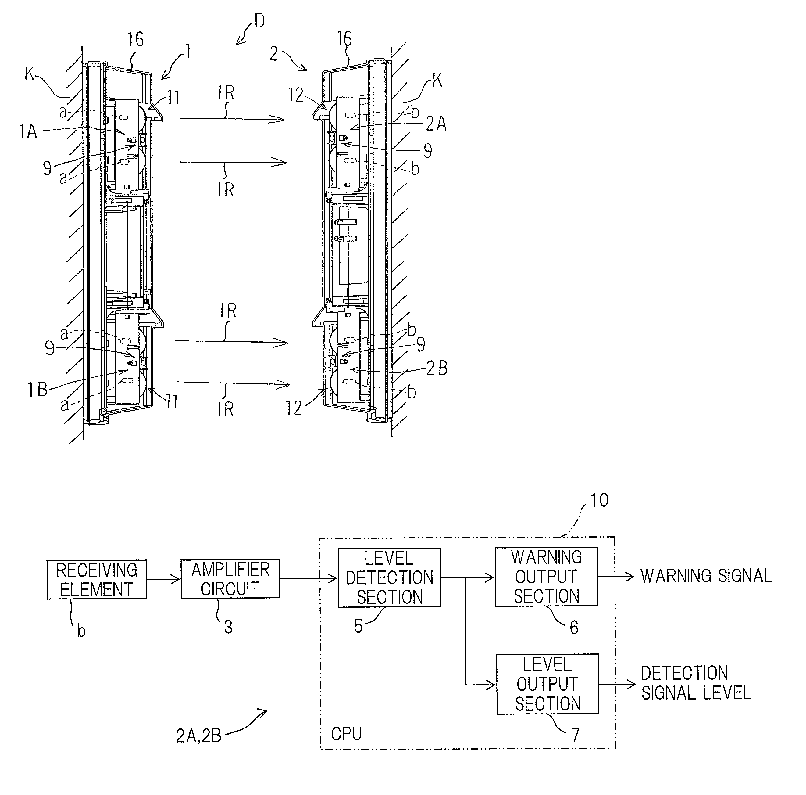
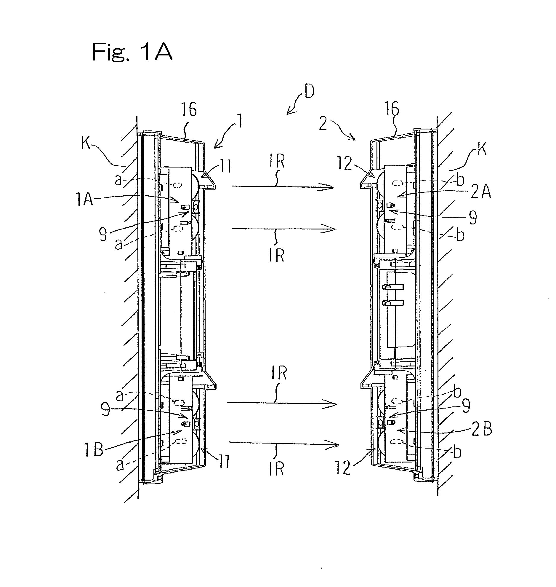
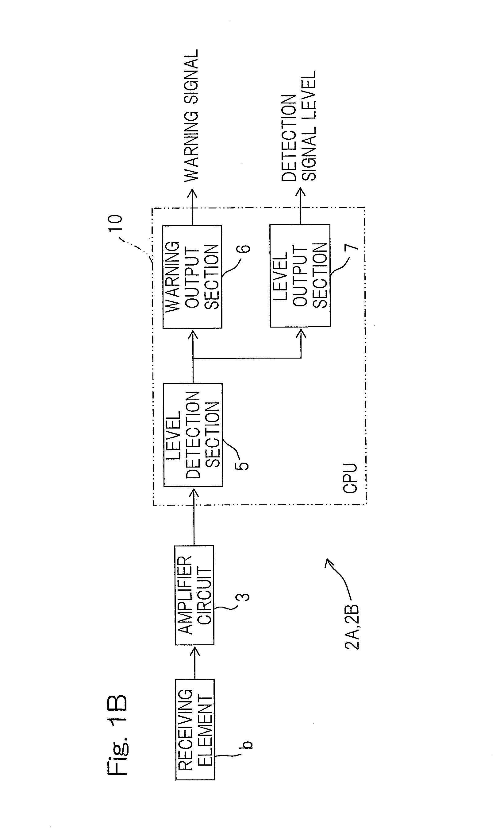
[0036]Hereinafter, preferred embodiments of the present invention will be described with reference to the drawings. FIG. 1A is a schematic side view of an object detection device having an angle adjustment mechanism according to the present invention. An object detection device D includes: a transmission section 1 having a transmitter 1A and a transmitter 1B; and a reception section 2 having a receiver 2A and a receiver 2B. Each of the transmitter 1A and the transmitter 1B includes transmitting elements a. The transmitters 1A and 1B are disposed one above the other. In the present embodiment, the transmitter 1A is disposed above the transmitter 1B. The receiver 2A and the receiver 2B are disposed so as to oppose the transmitter 1A and the transmitter 1B, and each include receiving elements b for receiving detection beams such as infrared rays (IR) transmitted from the transmitters 1A and 1B. The receivers 2A and 2B are disposed one above the other. In the present embodiment, the rec...

second embodiment

[0060]FIG. 6 is a perspective view of an object detection system according to the present invention. The object detection system includes: the automatic angle adjustment unit 70 that is engaged with the angle adjustment mechanism 30 of the receiver 2A of the object detection device D, and that adjusts an angle of the optical system 12 to the horizontal axis and an angle of the optical system 12 to the vertical axis, to automatically adjust the optical axis from the exterior of the device; and a control box 71 for controlling the automatic angle adjustment unit 70, in addition to the object detection device D. The control box 71 includes a probe P for input of a detection signal level. The automatic angle adjustment unit 70 includes: engagement-drive transmission sections 72 and 73 acting as horizontal and vertical adjustment gears that removably engage with the horizontal and the vertical adjustment dials 33 and 37 of the angle adjustment mechanism 30 of the receiver 2A, from the fr...


PUM


Abstract

An automatic angle adjustment unit (70) engages with and drivers a horizontal adjustment-engagement member (33) and a vertical adjustment-engagement member (37) of an object detection device (D) from the exterior. The unit (70) includes: engagement-drive transmission sections (72 and 73) which removably engages with both adjustment-engagement members (33 and 37), from the front surface, and drives both adjustment-engagement members (33 and 37); clamping section (76) that is removably secured to the object detection device (D); and an adjustment unit control section (80) for performing a control for adjusting a horizontal angle and a vertical angle of an optical system, based on a detection signal level.

Description

CROSS REFERENCE TO THE RELATED APPLICATION[0001]This application is based on and claims Convention priority to Japanese patent application No. 2011-246779, filed Nov. 10, 2011, the entire disclosure of which is herein incorporated by reference as a part of this application.BACKGROUND OF THE INVENTION[0002]1. Field of the Invention[0003]The present invention relates to an automatic angle adjustment unit that automatically adjusts angles of a detection unit from the exterior, for an object detection device which receives, by section of a receiver, detection beams transmitted from a transmitter and detects for an object based on the reception level.[0004]2. Description of Related Art[0005]In general, a transmitter-receiver opposing type object detection device includes: a transmitter having a transmitting optical system (detection unit) for transmitting detection beams, such as infrared rays, for object detection; and a receiver that is disposed so as to oppose the transmitter and has ...

Claims


Application Information

Patent Timeline
IPC IPC(8): G01B11/26
CPCG08B13/183G01V8/20H04B10/1143G01B11/26H04B10/1123G08B29/22G01S17/88G05D3/00
Inventor IKEDA, HIROYUKI
Owner OPTEX CO LTD
Why Eureka
Try Eureka