While some of these stents are flexible and have the appropriate radial rigidity needed to hold open a vessel or artery, there typically is a tradeoff between flexibility and radial strength and the ability to tightly compress or
crimp the
stent onto a
catheter so that it does not move relative to the
catheter or dislodge prematurely prior to controlled implantation in a vessel.
While this
stent pattern performs well in terms of traditional stent
metrics, it experiences one key tradeoff, namely it will excessively shorten under modest longitudinal compressive loads.
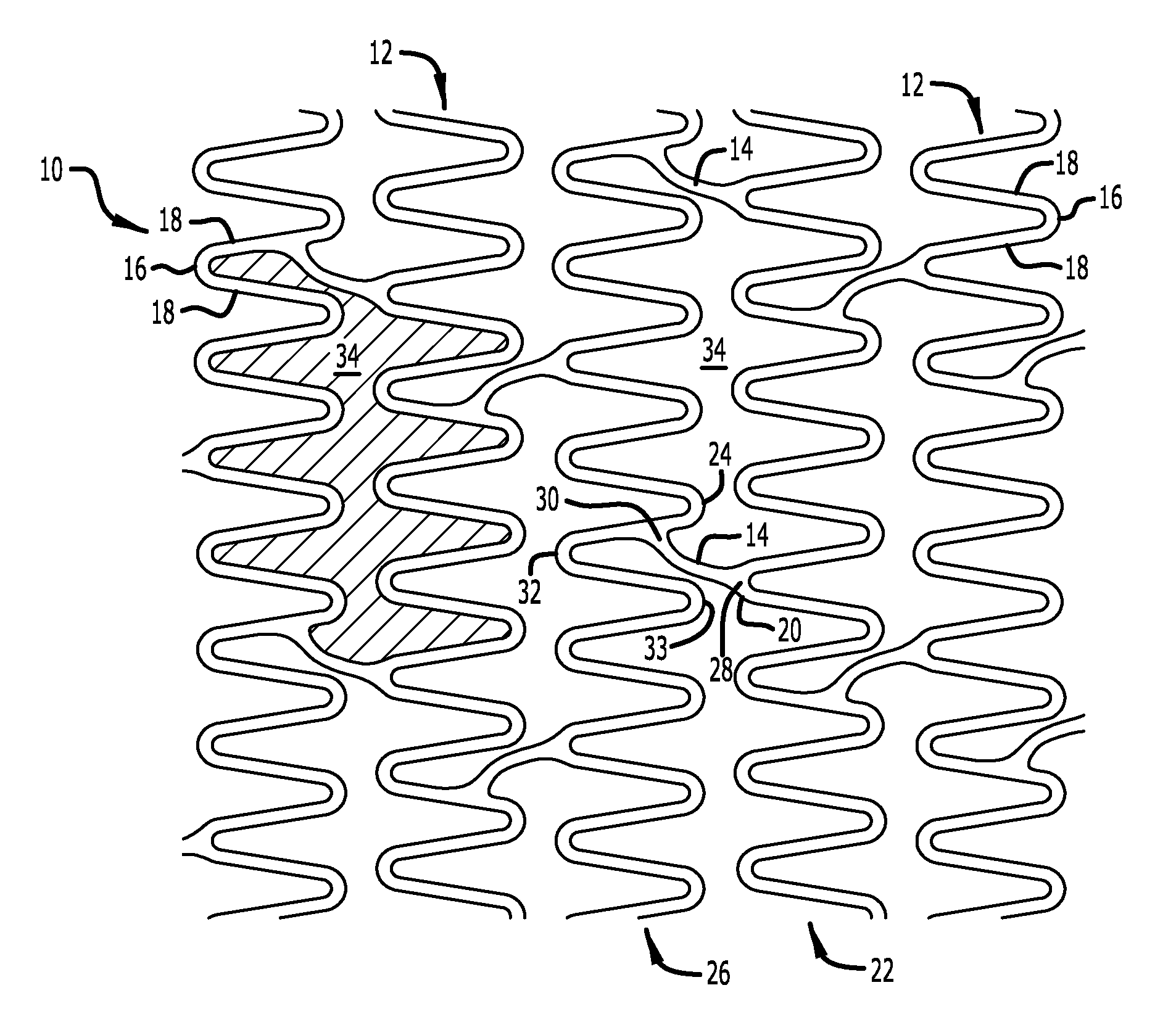
Two-link stents, specifically offset peak-to-peak, where the peaks of adjacent rings point toward each other but are slightly offset circumferentially, excessively shorten under modest (clinically relevant) longitudinal compressive loads.
This creates unwanted implications for safety and
efficacy of the stent
implant.
Specific reasons identified for this longitudinal
instability and / or poor longitudinal stiffness are complex as set forth below:(1) Insufficient number of links to bear a clinically relevant longitudinally
compressive load;(a) Two-link designs provide only two paths for longitudinal load to react through the stent structure.(b) Sub-optimal placement of load-bearing links.(2) Excessively unsupported ring structure deforms easily under longitudinally compressive loads;(a) Substantial unsupported ring structure exists between links in a specific ring (
cantilever effect);(b) Unevenly or misaligned expanded stent structure encourages adjacent rings / crests to
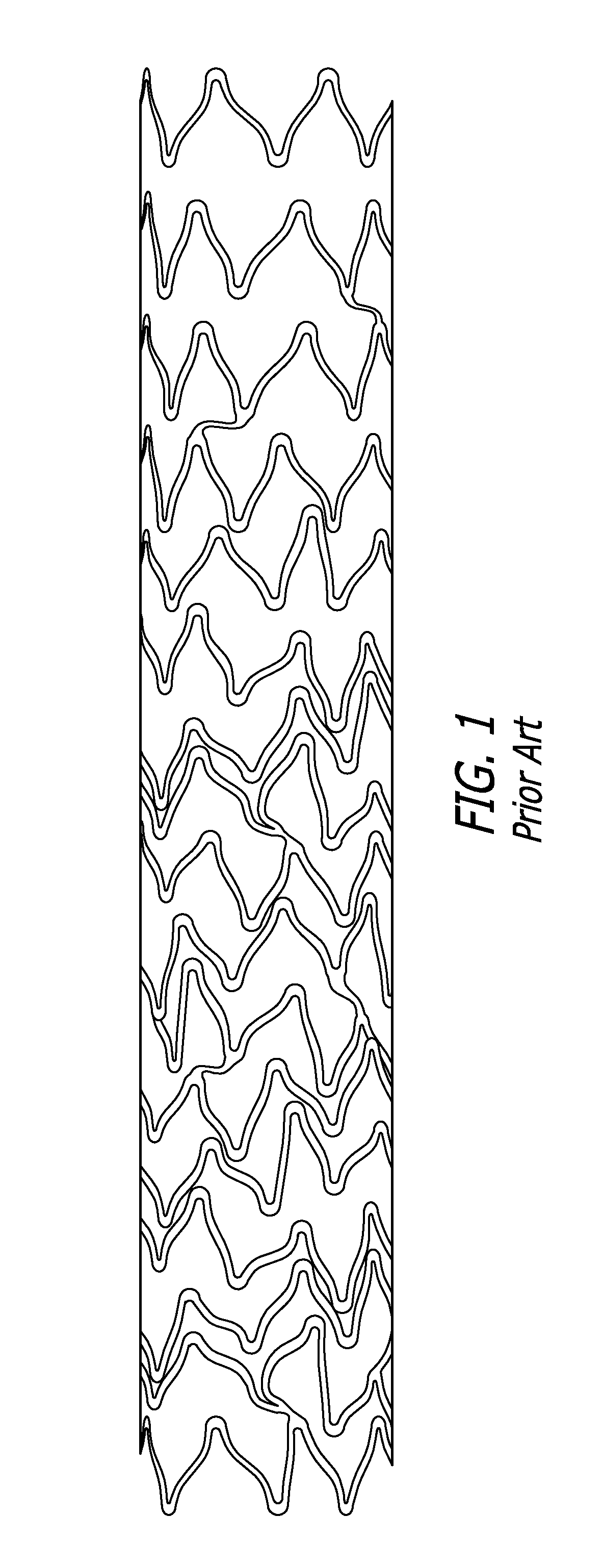
nest within each other without experiencing any substantial resistance until the structure has compressed excessively;(c) The combination of both above reasons under heading (2) exacerbates longitudinal
instability and produces substantial nesting as shown on a compressed stent (see the prior art stent of FIG. 1).(3) Offset and angled link designs lend readily to collapse behavior, as links do not provide resistance in direction of load;(a) Offset link designs create a
bending moment effect, which encourages the bar arms adjacent to link structures to bend and swing excessively (stress is focused in these bar arms as shown in FIG. 4);(b) Offset link designs create a structure that does not experience strut-to-strut contact during longitudinal compression; other peak-to-peak designs exhibit increased longitudinal stiffness by reacting load between adjacent rings during strut-to-strut contact; however, this is not the case for offset peak-to-peak designs;(4) Peak-to-peak patterns inherently shorten when expanded; if this shortening is prevented due to
balloon growth or friction, the structure may retain
residual stress that encourages a sudden shortening behavior under longitudinal compression loads.
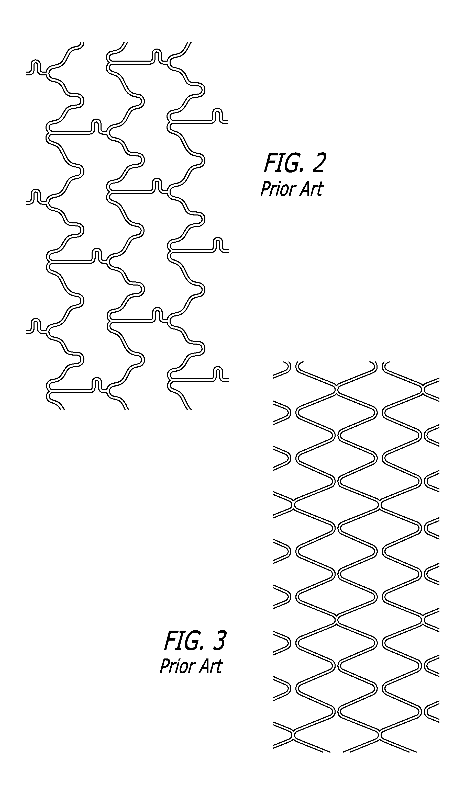
Non-offset peak-to-peak designs exhibit increased longitudinal stiffness by redirecting the load between adjacent rings through strut-to-strut contact (e.g., Medtronic Driver stent); however, this is not the case for offset peak-to-peak stents (e.g., Boston Scientific Element stent).
The uncompressed image (FIG. 9A) of an expanded offset peak-to-peak stent shows some deformation, however, the compressed image (FIG. 9B) shows substantial localized bending stresses and deformation in the bar arms adjacent to the stent links, as well as undesirable nesting of rings within adjacent rings without substantial strut-to-strut contact.

