

Production method of scintillator array
- Summary
- Abstract
- Description
- Claims
- Application Information
AI Technical Summary
Benefits of technology
Problems solved by technology
Method used
Image

Examples
first embodiment
[1] First Embodiment
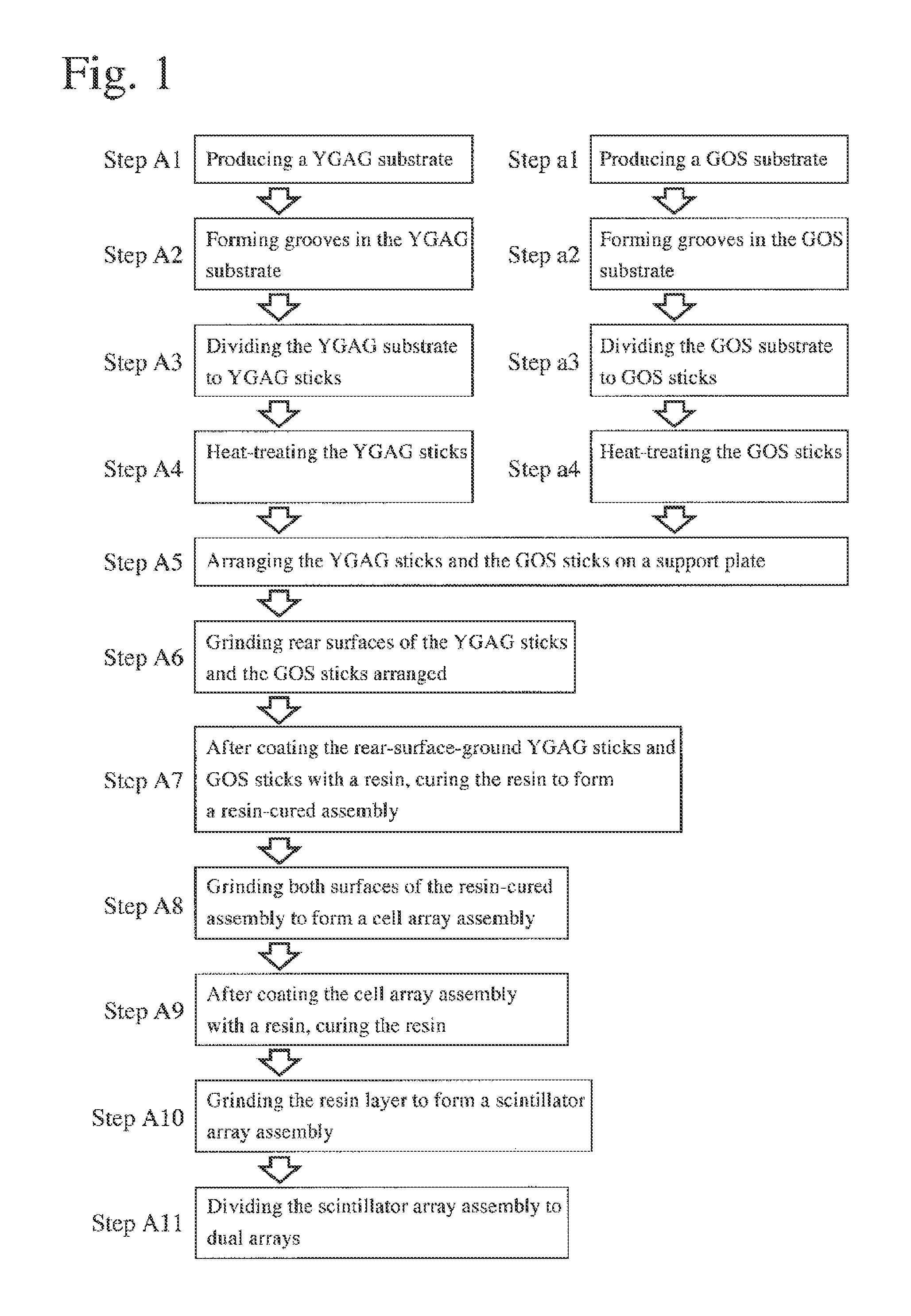
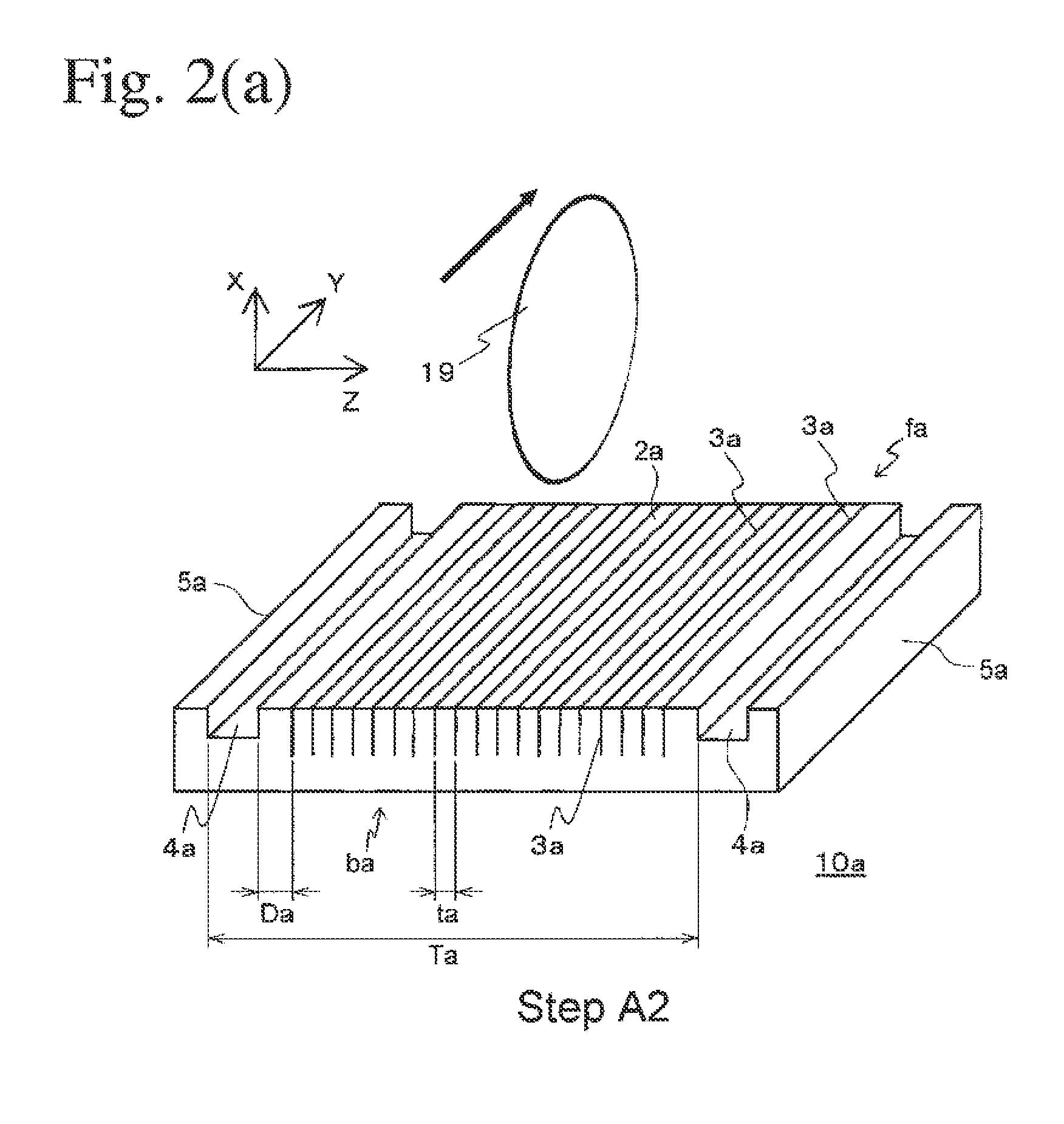
[0045]FIG. 1 is a flow chart showing the production method of a scintillator array according to the first embodiment of the present invention. A rectangular-plate-shaped YGAG substrate 10a formed by a sintered scintillator having a composition of yttrium-gadolinium-aluminum-gallium garnet (YGAG) and activated by an element Ce is first produced (step A1). As shown in FIG. 2(a), pluralities of parallel grooves 3a are then formed on one side of the YGAG substrate 10a by a rotating grinder 19 (step A2). The depth of each groove 3a is preferably about 60-90% of the thickness of the YGAG substrate 10a. Each portion between adjacent grooves 3a constitutes a YGAG cell portion 2a. Though each groove 3a is drawn by a line for simplicity in FIG. 2(a), it actually has a sufficient width relative to each cell portion 2d as shown in FIG. 11. The width of each groove 3a is preferably about 1-10% of the width of each cell portion 2a. Each groove 3a is preferably in parallel to o...
second embodiment
[2] Second Embodiment
[0073]Because the production method of a scintillator array according to the second embodiment of the present invention is the same as the method of the first embodiment except for part of the steps, explanations of the same steps will be omitted. Accordingly, with respect to the steps whose explanations are omitted, please refer to the explanations in the first embodiment.
[0074]Up to the steps A1, A2 and a1, a2, it is the same as the first embodiment. In the steps A3 and a3, the YGAG stick 10b is cut by a rotating grinder 19 to a width (d1+a grinding margin), and the GOS stick 20b is cut to a width (d2+a grinding margin). Side surfaces of YGAG sticks 10b and GOS sticks 20b obtained by cutting the YGAG substrate 10a and the GOS substrate 20a each having a rectangular plate shape in the steps A3 and a3 are ground to precisely adjust their widths to d1 and d2, respectively. Alternatively, side surfaces of YGAG sticks 10b and GOS sticks 20b obtained by cutting the ...
third embodiment
[3] Third Embodiment
[0076]FIG. 12 is a flow chart showing the production method of a scintillator array according to the third embodiment of the present invention. The method of the third embodiment is the same as that of the first embodiment up to the step A7, but different from that of the first embodiment except for changing the step A8 to a step A8-2 and omitting the steps A9 and A10.
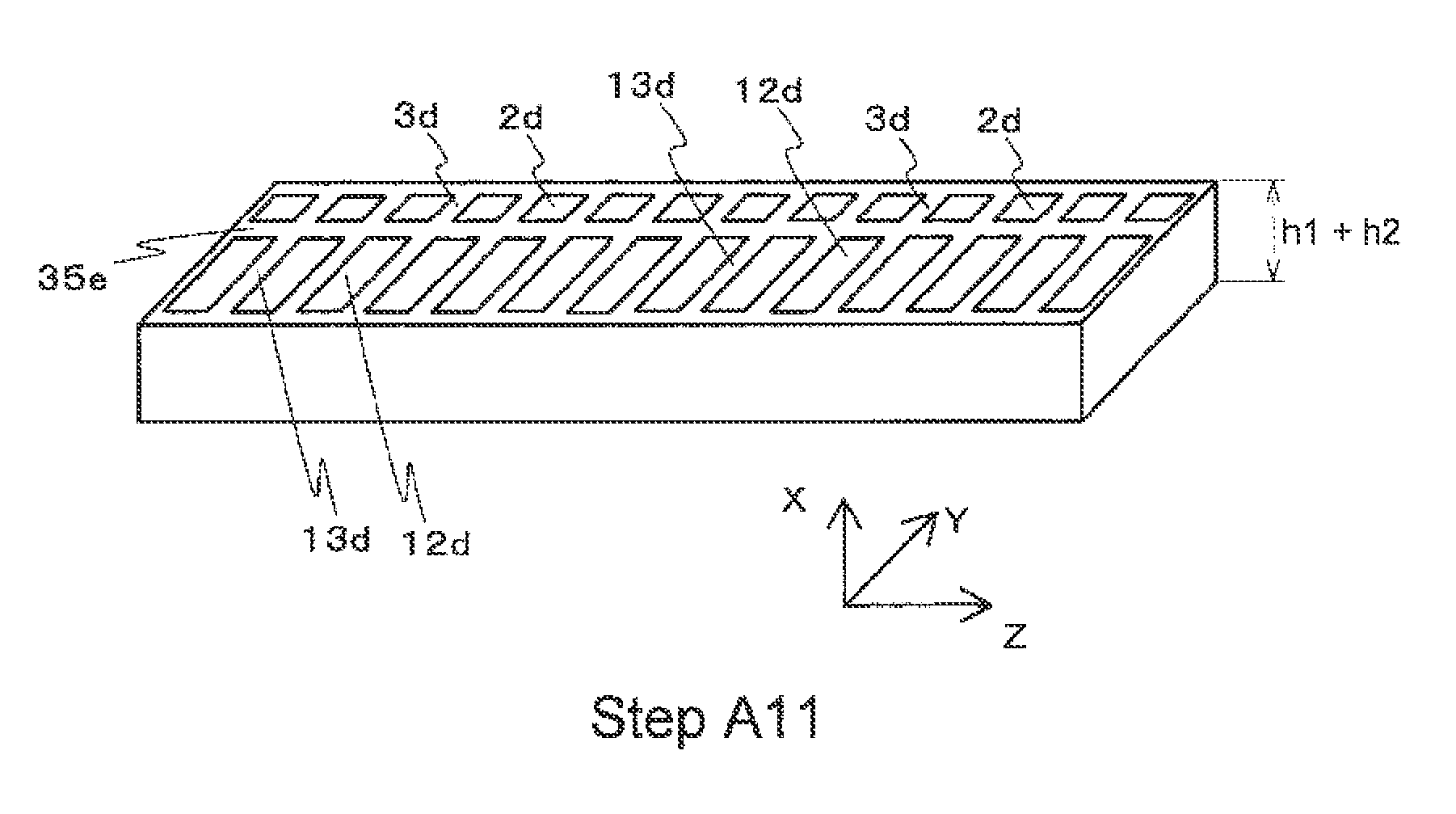
[0077]After the step A7, the resin-storing films 31F, 31R, 31B, 31L and the first support plate 30 are removed to obtain the resin-cured assembly 33 shown in FIG. 7. To remove a thin adhesive member remaining on a lower surface of the resin-cured assembly, grinding is conducted. Grinding is also conducted on a rear surface bs1 of the resin-cured assembly, to remove part of the resin 32 on the rear surface to a thickness of (h1+h2) (step A8-2). This grinding of both surfaces provides a resin-coated cell array assembly comprising a reflector having a thickness h2 on the rear surface side.
[0078]The res...
PUM
| Property | Measurement | Unit |
|---|---|---|
| Thickness | aaaaa | aaaaa |
| Color | aaaaa | aaaaa |
| Width | aaaaa | aaaaa |
Abstract
Description
Claims
Application Information