

Work vehicle
a technology for working vehicles and fuel pumps, which is applied in mechanical equipment, gearing details, transportation and packaging, etc., can solve the problems of sucking in foreign substances such as metal abrasion powder and the like in the reservoir space, tendency of large size, and easy sucking of fuel pumps, so as to simplify the structure of supplying and discharging reservoir oil with respect to the lifting valve
- Summary
- Abstract
- Description
- Claims
- Application Information
AI Technical Summary
Benefits of technology
Problems solved by technology
Method used
Image

Examples
first alternative embodiment
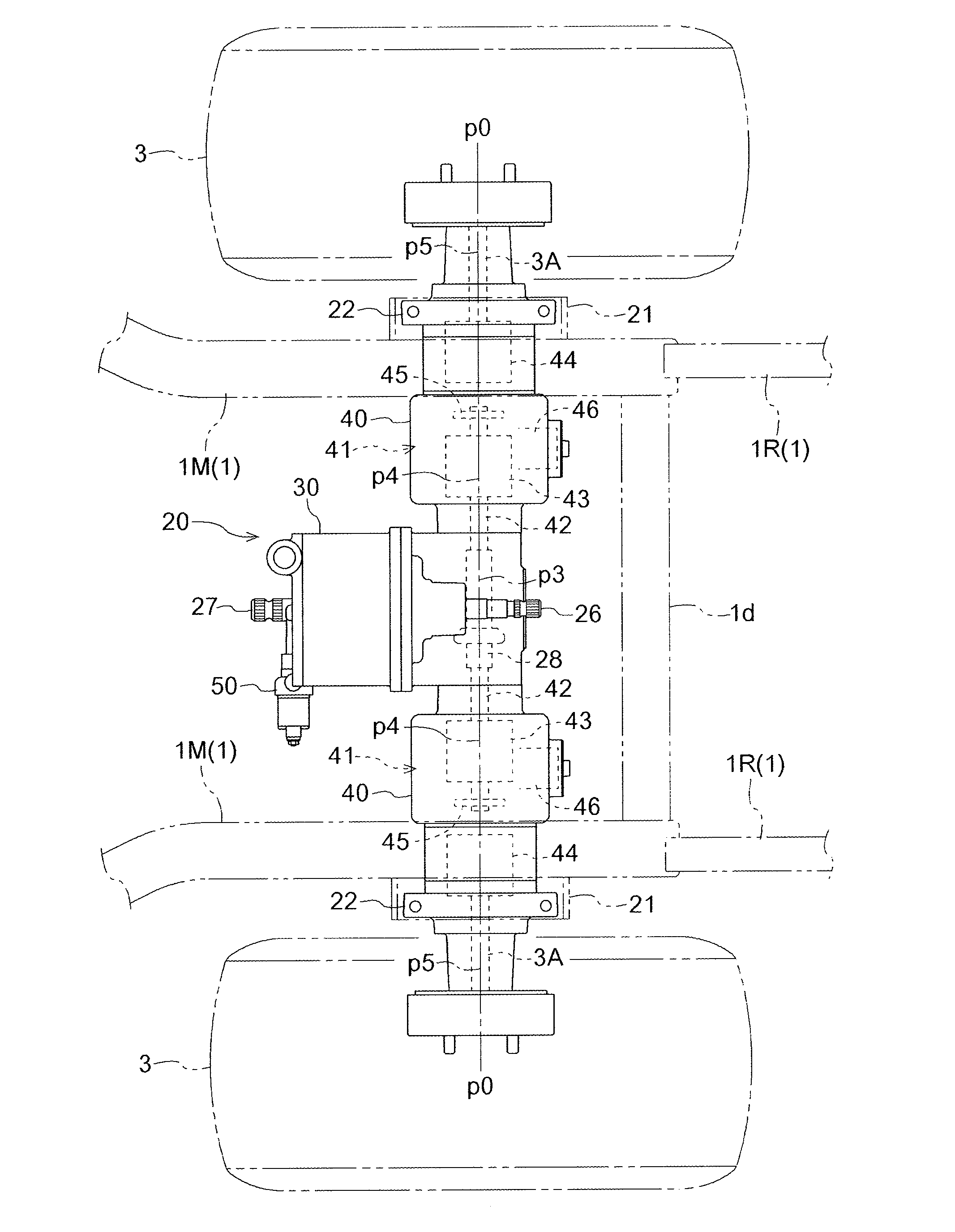
[0069]In the above-described embodiment, it is described that the hydraulic continuously variable transmission 41 provided in each of the axle cases 40 of the rear wheel drive unit 20 is configured by a pump motor of an internal gear type gerotor structure. However, the present invention is not limited to this. For example, as illustrated in FIG. 8, instead of having an internal gear type gerotor structure, the hydraulic continuously variable transmission 41 may also be configured using a pump 43 and a motor 44 arranged in a manner having a pump shaft and a motor shaft positioned on the same axis p4. In this case, it is desirable that the axis p4 of the pump 43 and the motor 44 be arranged in the axle case 40 on the same straight line p0 with respect to the axis p5 of the axle 3A and the axis p3 of the branch transmission shaft 28. Other configurations are configured the same way as in the above-described embodiment.
second alternative embodiment
[0070]In the above-described embodiment, it is described that the hydraulic continuously variable transmission 41 provided in each of the axle cases 40 of the rear wheel drive unit 20 is configured by a pump motor of an internal gear type gerotor structure. However, the present invention is not limited to this. For example, as illustrated in FIG. 9, the hydraulic continuously variable transmission 41 may also be configured by a pump 43 and a motor 44, the pump 43 being provided with an input shaft 42 having an axis p4 positioned on the same straight line p0 as the axis p3 of the branch transmission shaft 28, and the motor 44 being provided with an output shaft 44a parallel to the input shaft 42 of the pump 43. The hydraulic continuously variable transmission 41 may be configured in such a manner that the driving force is transmitted from the output shaft 44a of the motor 44 via a second reduction gear mechanism 47 to the axle 3A. In this case, it is desirable that the output shaft 4...
third alternative embodiment
[0071]In the above-described embodiment, it is described that, in the control valve unit 50, as illustrated in FIG. 7, the control valve 51 of the circuit d and the switching valve 54 of the circuit e are respectively mechanically linked to the lift operation lever 64 and the PTO clutch lever 65, the circuit d supplying hydraulic oil to the hydraulic cylinder 15 that operates the lift arm 14 for lifting the mower, and the circuit e supplying hydraulic oil to the PTO clutch 35. However, the present invention is not limited to this. For example, as illustrated in FIG. 10, the control valve 51 may be configured by a valve 52 for rising and a valve 53 for lowering that use electromagnetic solenoids, and the switching valve 54 may also be configured by a structure that uses an electromagnetic solenoid, and these may be electrically linked. In this case, operation positions of the lift operation lever 64 and operations positions of the PTO clutch lever 65, although not illustrated in the ...
PUM
 Abstract
Description
Claims
Application Information