Latent heat exchanger in condensing boiler

Inactive Publication Date: 2013-05-23
KYUNGDONG NAVIEN
View PDF7 Cites 11 Cited by
  • Summary
  • Abstract
  • Description
  • Claims
  • Application Information

AI Technical Summary

Benefits of technology

[0036]According to the a latent heat exchanger of a condensing boiler of the present invention, a plurality of tubes are vertically installed on front and rear inner sides of the latent heat exchanger so as to be inclined downwardly, thereby allowing an exhaust direction of a combustion product and a discharge direction of condensed water to be identical to reduce exhaust resistance of the combustion product and to smoothly discharge the condensed water.
[0

Problems solved by technology

Thus, the boilers were very low in heat efficiency, and required a long time to obtain high-temperature heating water.
For this reason, the latent heat recollected by the condensation is again discharged in an evaporation heat form, and thus it is impossible to obtain maximum condensation efficiency.
This downward combustion type condensing boiler is estimated to be a most preferable condensing boiler from the viewpoint of a structure capable of recollecting the most latent heat, but it is accompa

Method used


Image

  • Latent heat exchanger in condensing boiler
  • Latent heat exchanger in condensing boiler
  • Latent heat exchanger in condensing boiler

Examples


Embodiment Construction

[0046]Hereinafter, exemplary embodiments of the present invention will be described in detail with reference to the accompanying drawings. Here, the same reference numerals will be used to denote components having the same function and operation as those in the related art.

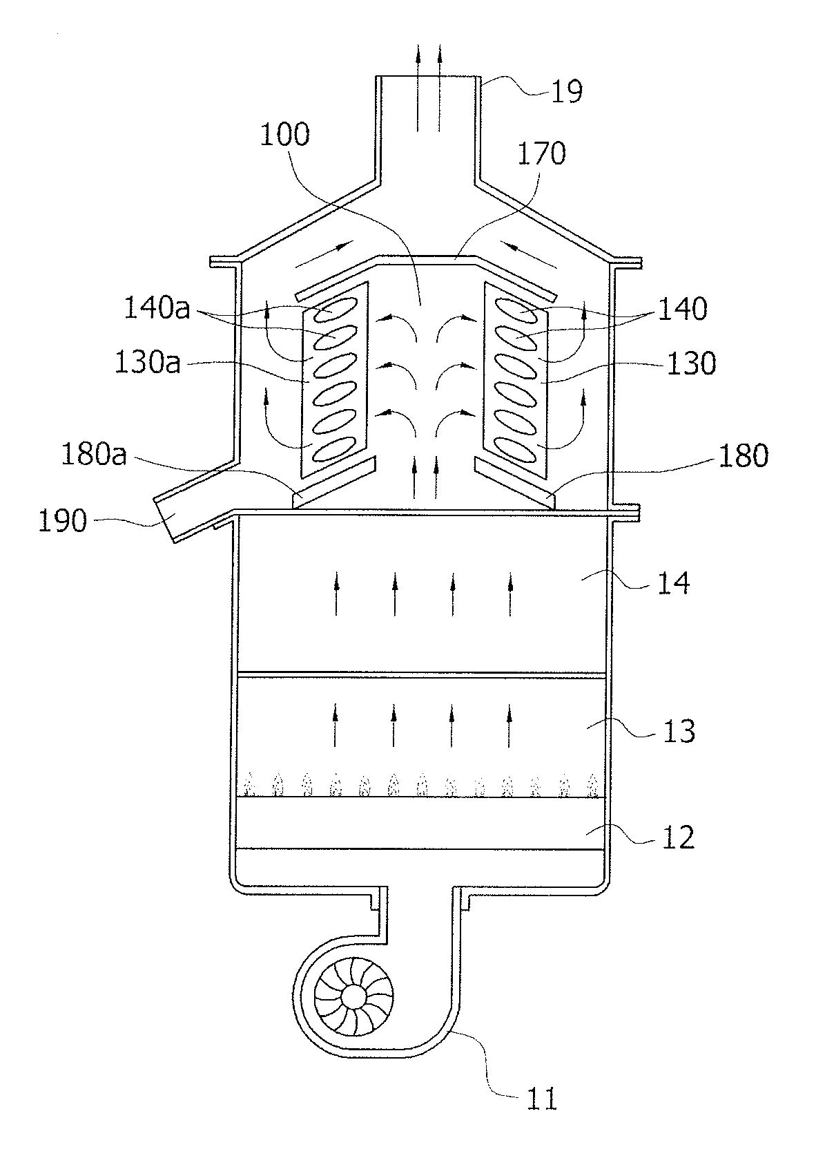
[0047]FIG. 3 is a schematic view showing a structure of a condensing boiler to which the present invention is applied, and FIG. 4 is a longitudinal sectional view of FIG. 3. FIGS. 3 and 4 show the condensing boiler when viewed from the left.

[0048]The condensing boiler according to an embodiment of the present invention is configured so that an upward combustion type burner 12 and a combustion chamber 13 are installed on an upper side of a blower 11 so that a flame is formed upwardly, so that a sensible heat exchanger 14 absorbing combustion sensible heat generated from the burner 12, a latent heat exchanger 100 absorbing latent heat of water vapor contained in a combustion product (exhaust gas) heat-exchanged by t...


PUM


Abstract

A latent heat exchanger of a condensing boiler, in which the condensing boiler includes a sensible heat exchanger absorbing combustion sensible heat generated by a burner, a latent heat exchanger absorbing latent heat of water vapor contained in a combustion product heat-exchanged by the sensible heat exchanger, an exhaust hood discharging the combustion product flowing through the latent heat exchanger, and a condensed water outlet discharging condensed water generated from the latent heat exchanger. In the latent heat exchanger the combustion product burnt by the burner flows through the sensible heat exchanger, is vertically raised toward the latent heat exchanger, is slantingly lowered in an outward direction at an acute angle from a horizontal plane, is heat-exchanged by the latent heat exchanger, is vertically raised, and is discharged to the exhaust hood.

Description

TECHNICAL FIELD[0001]The present invention relates generally to a latent heat exchanger of a condensing boiler and, more particularly, to a latent heat exchanger of a condensing boiler, which allows an exhaust direction of a combustion product and a discharge direction of condensed water to be identical to reduce exhaust resistance of the combustion product and to smoothly discharge the condensed water generated from the latent heat exchanger, and which has a simple coupling internal structure.BACKGROUND ART[0002]Boilers are apparatuses that make a desired area warm by heating a heat medium in a closed container with a heat source, and are each made up of a burner burning fuel and a heat exchanger exchanging heat between burnt high-temperature combustion air and heating water.[0003]Earlier heat exchangers of boilers used only sensible heat generated during combustion of the burner, and discharged the high-temperature combustion air through an exhaust hood. Thus, the boilers were ver...

Claims


Application Information

Patent Timeline
IPC IPC(8): F24H8/00
CPCY02B30/106F24H8/00F24H8/006Y02B30/102F28D7/1692F28D21/0007F28D7/1623Y02B30/00
Inventor MIN, TAE-SIK
Owner KYUNGDONG NAVIEN
Why Eureka
Try Eureka