
System for manipulating samples in liquid droplets

a liquid droplet and sample technology, applied in the field of liquid droplet sample manipulation system, can solve the problems of large system that is not designed to be portable, investigators or technical lab staff still need to intervene, and none of the above-cited devices allows the full automatic processing of nucleic acids

Active Publication Date: 2013-05-23
TECAN TRADING AG
View PDF3 Cites 36 Cited by
  • Summary
  • Abstract
  • Description
  • Claims
  • Application Information

AI Technical Summary

Benefits of technology

The present invention is a liquid droplet manipulation system with an electrode array for manipulating samples in liquid droplets and optically inspecting them. The system includes a substrate with electrodes and a central control unit for selecting individual electrodes and providing voltage pulses for manipulating samples. The system can be used for manipulating samples in liquid droplets and optically inspecting them using an optical detection system. The system also includes a disposable cartridge with a working film for manipulating samples in liquid droplets. The cartridge can be preloaded with prepared treatment liquids and / or reagents for the planned assay. The system allows for individual manipulation of single droplets, separate reactions in each droplet, and processing each droplet differently and individually. The system also allows for processing some droplets for nucleic acid amplification and other droplets for immunoassay or reference samples.

Problems solved by technology

They are also larger systems that are not designed to be portable.
Although this cartridge provides a system to at least partially control the sample processing electronically, intervention of an investigator or of technical lab staff is still required.
However, none of the above cited devices allow the fully automated processing of nucleic acids starting from collected material up to the final analysis in the small volume scale.
An additional disadvantage of the presented devices comes with the nature of such arrangements of electrode arrays, being generally expensive in production, thus being rather non-disposable in use.
A continuous re-use of the same device for different biological samples and applications however bears the risk of cross-contaminating the samples of interest, which could lead to false results.
Therefore, such devices are not suited for high-throughput assays.

Method used


Image

  • System for manipulating samples in liquid droplets
  • System for manipulating samples in liquid droplets
  • System for manipulating samples in liquid droplets

Examples


first embodiment

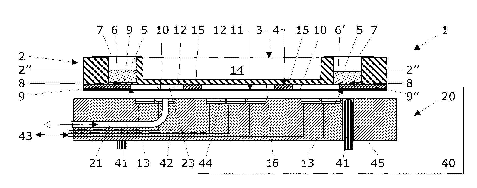
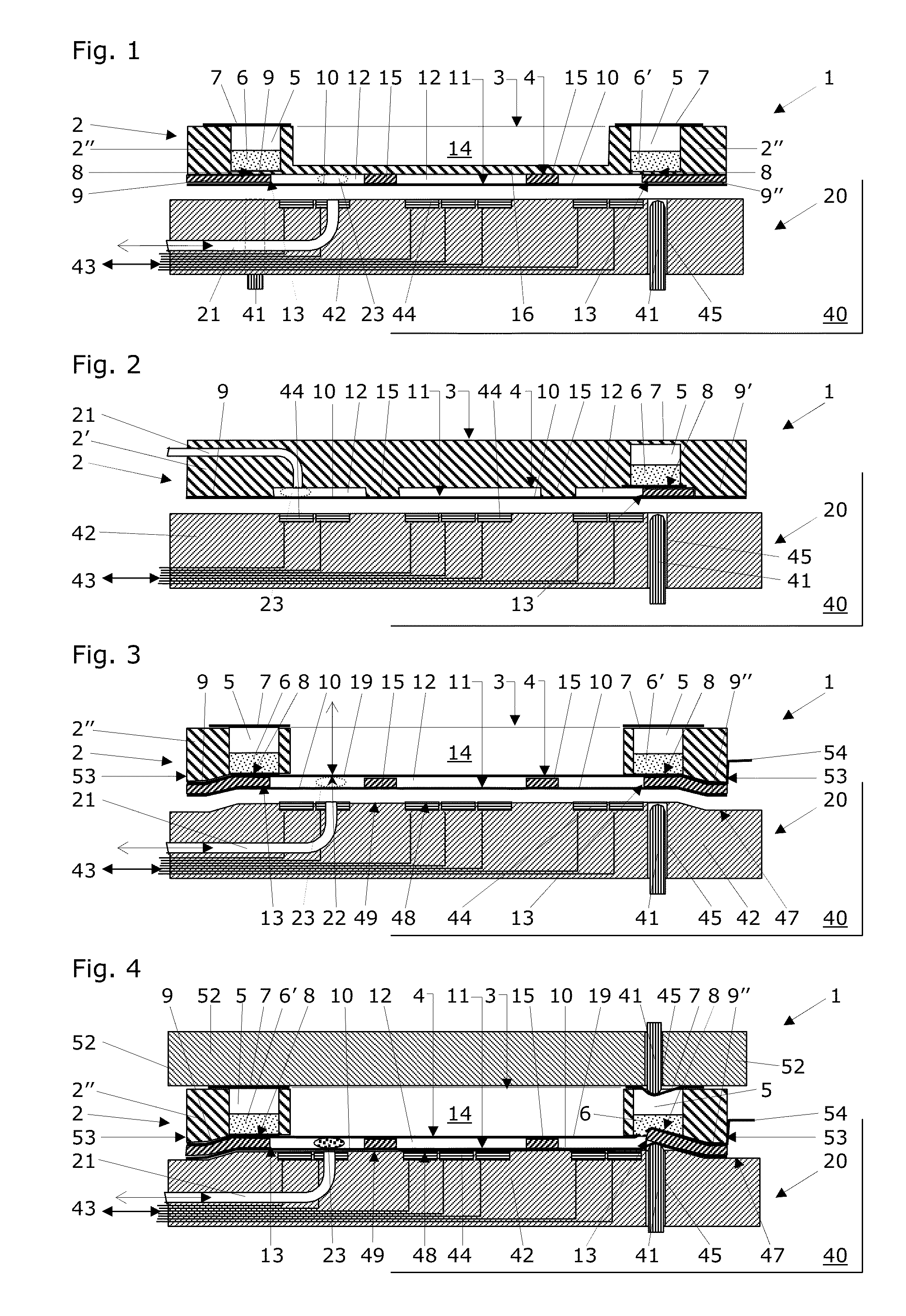
[0058]The FIG. 1 shows a vertical cross-section through a frame structured cartridge 1 with a central opening 14 closed by a bottom portion 16, with a number of wells 5 and a working film 10 contacted by a peripheral spacer 9 that is configured as a separate peripheral element 9″. The cartridge 1 is almost in contact with the electrode array 20 of a system 40 for liquid droplet manipulation.

[0059]This cartridge 1 comprises a working film 10 for manipulating samples in liquid droplets with an electrode array 20 when the working film 10 of the cartridge 1 is placed on said electrode array 20. This cartridge 1 also comprises a body 2, which body 2 preferably comprises an essentially flat lower surface 4. According to the first embodiment, the body 2 is configured as a frame structure 2″ with a central opening 14. The body 2 comprises an upper surface 3, a lower surface 4, and a number of wells 5 configured to hold therein reagents 6 or samples 6′. Preferably the material of the body 2...

third embodiment

[0085]FIG. 3 shows a vertical cross-section through a frame structured cartridge 1 with a central opening 14 across the entire height of the body 2. The cartridge 1 comprises a number of wells 5 and a working film 10 contacted by a spacer 9 that is configured as a separate peripheral element 9″. The cartridge 1 is almost in contact with the electrode array 20 of a system 40 for liquid droplet manipulation.

[0086]This cartridge 1 comprises a working film 10 for manipulating samples in liquid droplets with an electrode array 20 when the working film 10 of the cartridge 1 is placed on said electrode array 20. This cartridge 1 also comprises a body 2, which body 2 preferably comprises an essentially flat lower surface 4. According to the third embodiment, the body 2 is configured as a frame structure 2″ with a central opening 14 that extends across the entire height of the body 2. The body 2 comprises an upper surface 3, a lower surface 4, and a number of wells 5 configured to hold ther...

fourth embodiment

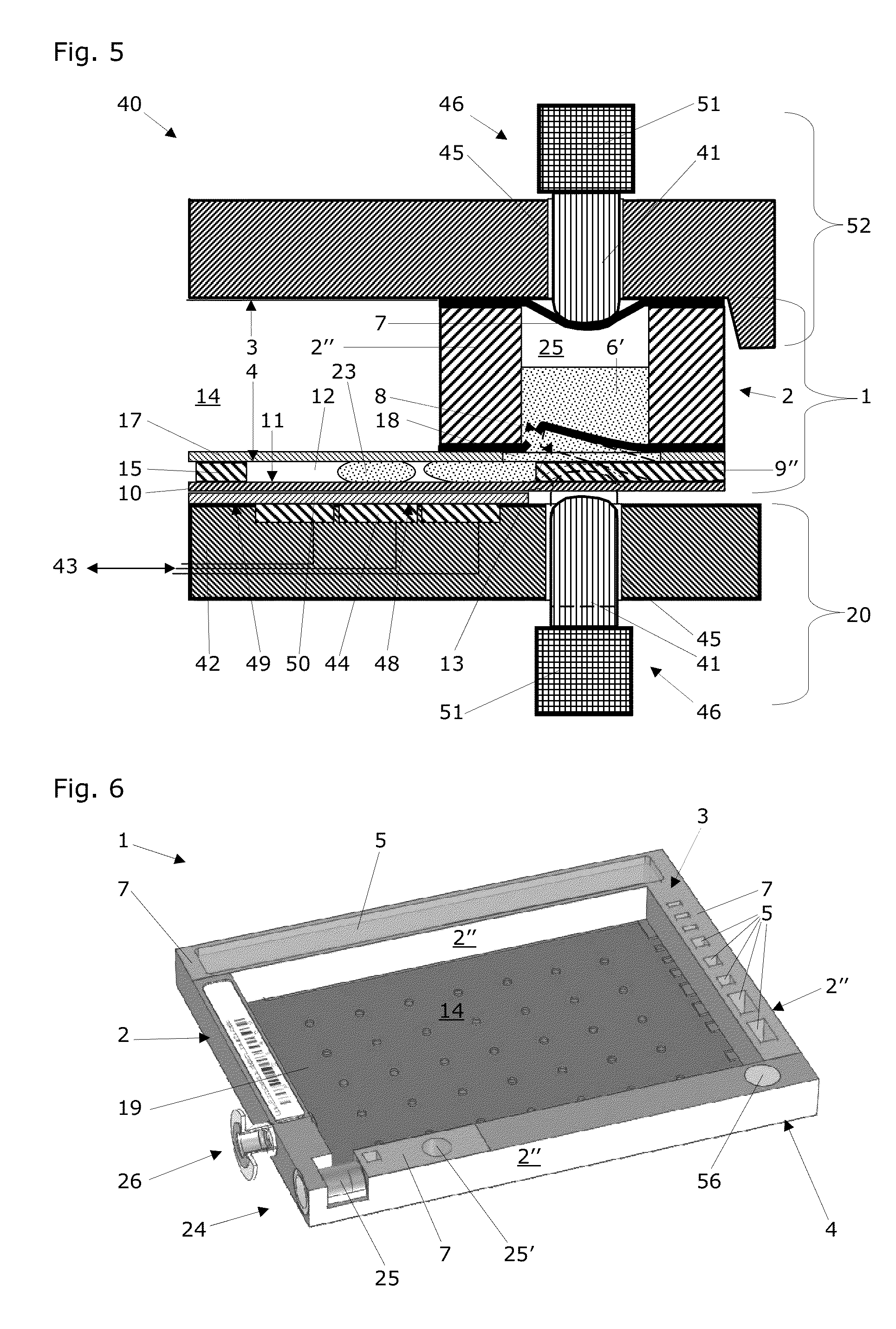
[0103]FIG. 5 shows a vertical cross-section through a frame structured cartridge 1 with a central opening 14 across the body 2, with a number of wells 5 and a working film 10 contacted by a separate peripheral spacer element 9″. The cartridge 1 is in contact with the electrode array 20 of a system 40 for liquid droplet manipulation. The piercable bottom structure 8 of one well (the intake recess 25) is opened and some of its content is pressed into the gap 12 between the working film 10 and a cover layer 19 that is configured as a rigid cover 17 here. The material for this rigid cover preferably is Mylar®, a transparent, flexible polyester foil on the basis of polyethylene terephthalat from DuPont. The rigid cover 17 may be coated on its underside with a layer of indium tin oxide (ITO) in order to provide the rigid cover 17 with an electrically conductive layer that can be connected to a ground potential source of the system 40 for liquid droplet manipulation. This FIG. 5 also depi...


PUM

PropertyMeasurementUnit
volumeaaaaaaaaaa
temperatureaaaaaaaaaa

Abstract

A liquid droplet manipulation system has a substrate with at least one electrode array and a central control unit for controlling selection of individual electrodes of the electrode array and for providing the electrodes with individual voltage pulses for manipulating liquid droplets by electrowetting. A working film is placed on top of the electrodes for manipulating samples in liquid droplets with the electrode array. At least one selected individual electrode of the electrode array is configured to be penetrated by light of an optical detection system for the optical inspection or analysis of samples in liquid droplets that are located on the working film. Also disclosed is working film that is to be placed on the electrode array and a cartridge that includes such a working film for manipulating samples in liquid droplets.

Description

RELATED PATENT APPLICATIONS[0001]The present application is a Continuation in Part application of the applicant's copending, non-published patent application U.S. Ser. No. 13 / 188,584 of Jul. 22, 2011. The present application also relates to the non-published applications EP 12 174 408.0 of Jun. 29, 2012; JP 2012-148654 of Jul. 2, 2012; and CN 2012 10254865.1 of Jul. 23, 2012. The entire content of all these non-published applications is herein enclosed by explicit reference for all purposes.FIELD OF TECHNOLOGY[0002]The present invention relates to a liquid droplet manipulation system and to a cartridge with a polymer film for manipulating samples in liquid droplets thereon. The liquid droplet manipulation system may comprise such a cartridge, an electrode array supported by a substrate, and a central control unit for controlling the selection of individual electrodes and for providing them with individual voltage pulses for manipulating liquid droplets by electrowetting.[0003]The an...

Claims


Application Information

Patent Timeline
Patent Type & Authority Applications(United States)
IPC IPC(8): G01N27/447
CPCG01N27/44791B01L2400/0683B01L3/502738B01L3/502792B01L3/5029B01L3/523B01L3/527B01L7/52B01L2200/025B01L2200/027B01L2200/04B01L2200/0647B01L2200/141B01L2300/044B01L2300/0672B01L2300/0681B01L2300/0829B01L2300/0864B01L2300/0867B01L2300/0887B01L2300/089B01L2300/161B01L2400/0427B01L2400/043B01L2400/0478B01L3/502715
Inventor LEE, TRAVISFRANKLIN, MICHAEL BENJAMINWANG, KAILIANG
Owner TECAN TRADING AG
Learn More