LED power source with over-voltage protection

a technology of over-voltage protection and power source, which is applied in the direction of electric variable regulation, process and machine control, instruments, etc., can solve the problems of increased manufacturing costs, increased manufacturing costs, and/or reduced reliability, and is difficult to control

Active Publication Date: 2013-05-23
GENERAL ELECTRIC CO
View PDF9 Cites 71 Cited by
  • Summary
  • Abstract
  • Description
  • Claims
  • Application Information

AI Technical Summary

Benefits of technology

[0009]As described herein, the exemplary embodiments overcome one or more of the above or other disadvantages known in the art.

Problems solved by technology

An LLC resonant tank circuit typically operates at high frequencies and can be highly efficient but has some difficulties when operating under no-load conditions.
Various solutions to the no-load problems have been purposed, such as re-cycling the converter, but these solutions are difficult to control and reliability is a concern.
In any case, the addition of OVP comes with additional costs, including increased manufacturing costs, functional limitations, and / or reduced reliability.

Method used


Image

  • LED power source with over-voltage protection
  • LED power source with over-voltage protection
  • LED power source with over-voltage protection

Examples


Embodiment Construction

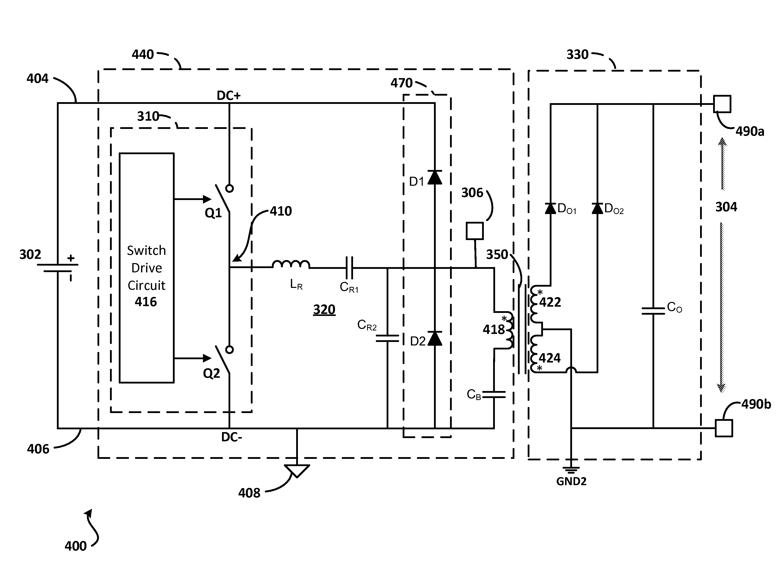
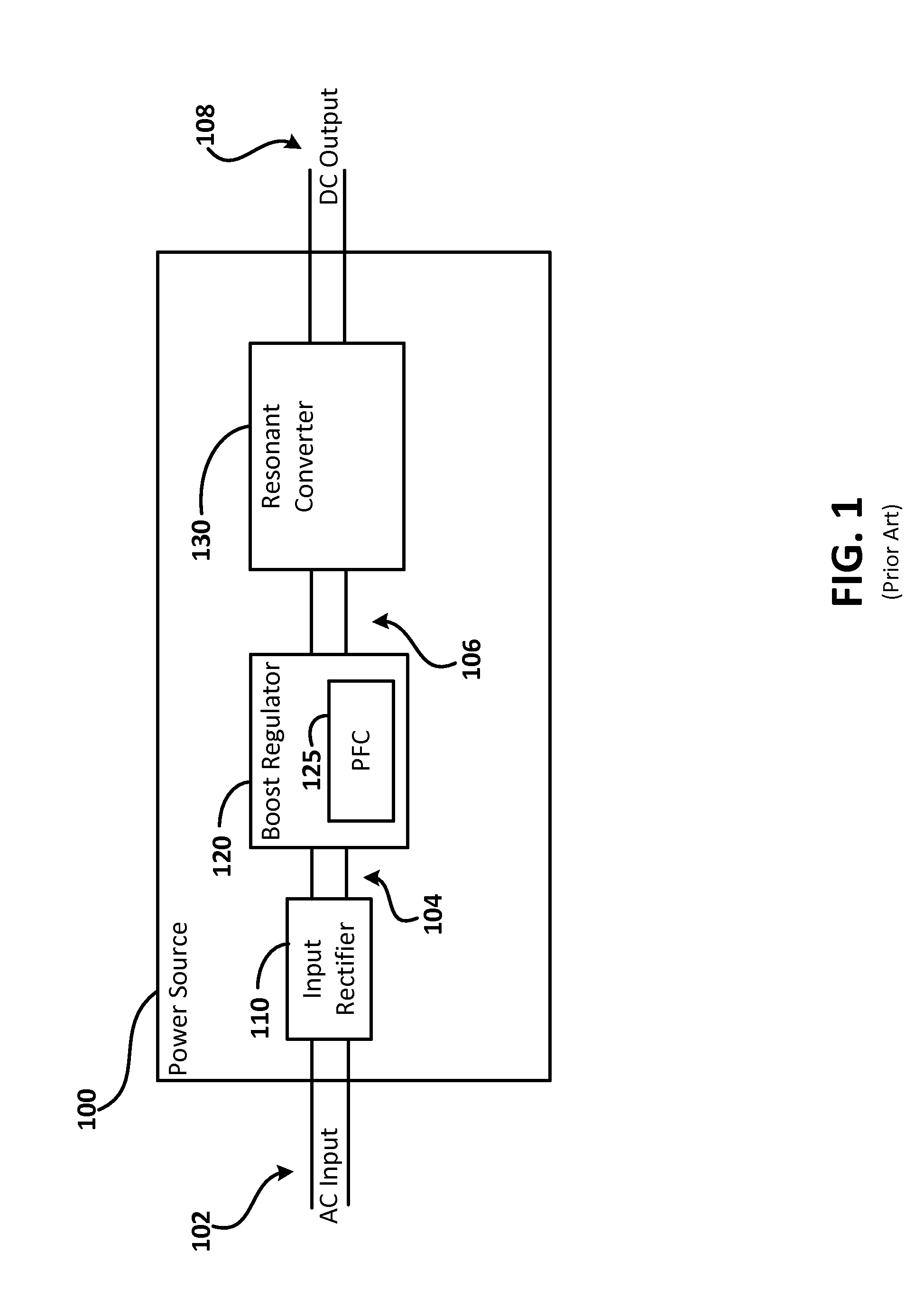
[0028]Referring now to the drawings there can be seen in FIG. 3 a block diagram of an exemplary isolated resonant DC-DC converter 300 incorporating aspects of the disclosed embodiments. The resonant converter 300 can be used in a power source 100 as is shown in FIG. 1 for operating Light Emitting Diode arrays and other class 2 apparatus, as is generally described herein. The aspects of the disclosed embodiments are generally directed to a power source that includes a resonant converter capable of providing isolated DC-DC conversion and over-voltage protection.

[0029]The isolated DC-DC converter 300 includes a half-bridge converter 310 and a resonant tank coupled through an output transformer 350 to an output rectifier / filter 330. A controller 340 receives information from the output rectifier 330 and is coupled to the self-oscillating inverter 310 through a feedback transformer 360 to provide closed loop control of the converter 300. The output transformer 350 and the feedback transf...


PUM


Abstract

A resonant DC-DC converter used to drive an LED array includes a half-bridge converter configured to receive DC input power and produce a square wave voltage. A resonant tank circuit that includes an inductive element, a first resonance capacitor, and a second resonance capacitor, is coupled to the half-bridge converter to receive the square wave voltage such that a generally sinusoidal AC voltage is produced across the second resonance capacitor. An output transformer with a primary winding and one or more secondary windings, is coupled in parallel to the second resonance capacitor, and a clipping circuit is coupled to the primary winding such that the voltage across the primary winding does not substantially exceed the voltage of the DC input power. An output rectifier is coupled to the one or more secondary windings of the output transformer and is configured to produce a generally DC output voltage.

Description

BACKGROUND[0001]1. Field of the Invention[0002]The aspects of the present disclosure relate generally to power supplies for electroluminescent devices and in particular to resonant power converters used to drive light emitting diode arrays.[0003]2. Description of Related Art[0004]Light Emitting Diode (LED) arrays, in which multiple LEDs are formed into an array and powered as a unit, are gaining popularity in lighting and signaling applications. LED arrays are typically connected to a direct current (DC) power source where the amount of applied current controls the brightness of emitted light. Switched mode power supplies are often used to provide power for LED arrays and other appliances requiring low level direct current (DC) power. Switched mode power supplies generally relate to a class of voltage regulation apparatus where input DC power is chopped by a switching circuit and fed into an energy storage device, usually an inductor. Energy from the chopped DC power is alternately ...

Claims


Application Information

Patent Timeline
Patent Type & Authority Applications(United States)
IPC IPC(8): H05B37/02H02M3/335H05B44/00
CPCH02M1/32H02M1/4258H05B33/0815Y02B70/126Y02B20/341Y02B20/348H05B33/089H05B45/382H05B45/355Y02B20/30Y02B70/10H05B45/38H05B45/39H05B47/24H02M3/33571H02M3/01
Inventor YAO, GANG
Owner GENERAL ELECTRIC CO
Why Eureka
Try Eureka