Magnetic field sensor including an anisotropic magnetoresistive magnetic sensor and a hall magnetic sensor

a magnetic sensor and anisotropic magnetoresistive technology, applied in the direction of magnetic sensor geometrical arrangement, three-component magnetometer, instruments, etc., can solve the problems of non-standard operation, circuit may prove technologically problematic, and the production of concentrators requires execution of non-standard technological processes with respect to traditional cmos processes, etc., to achieve high sensitivity and high assembly complexity

Inactive Publication Date: 2013-05-23
STMICROELECTRONICS SRL
View PDF5 Cites 9 Cited by
  • Summary
  • Abstract
  • Description
  • Claims
  • Application Information

AI Technical Summary

Benefits of technology

[0039]The triaxial sensor of an AMR type 30 is characterized by high sensitivity. However, since the first and second dice 32, 34 are set at 90°, it presents a high complexity of assembly and moreover requires a package having considerable overall dimensions.

Problems solved by technology

Generally, whereas the Wheatstone bridge 19, and hence the magnetoresistive elements 20, are formed in a first die, the reading circuit is formed in a second die, possibly together with an appropriate circuit designed to generate the supply voltage V. This is due to the fact that integration, within one and the same die, of the magnetoresistive elements 20 and of the reading circuit may prove technologically problematical, requiring non-standard operations.
However, the production of the concentrator requires execution of non-standard technological processes with respect to traditional CMOS processes.
In addition, the four Hall structures, which are basically four Hall sensors, do not have particularly high sensitivities, and are hence not suited for applications of a compass type.
However, since the first and second dice 32, 34 are set at 90°, it presents a high complexity of assembly and moreover requires a package having considerable overall dimensions.

Method used


Image

  • Magnetic field sensor including an anisotropic magnetoresistive magnetic sensor and a hall magnetic sensor
  • Magnetic field sensor including an anisotropic magnetoresistive magnetic sensor and a hall magnetic sensor
  • Magnetic field sensor including an anisotropic magnetoresistive magnetic sensor and a hall magnetic sensor

Examples


Embodiment Construction

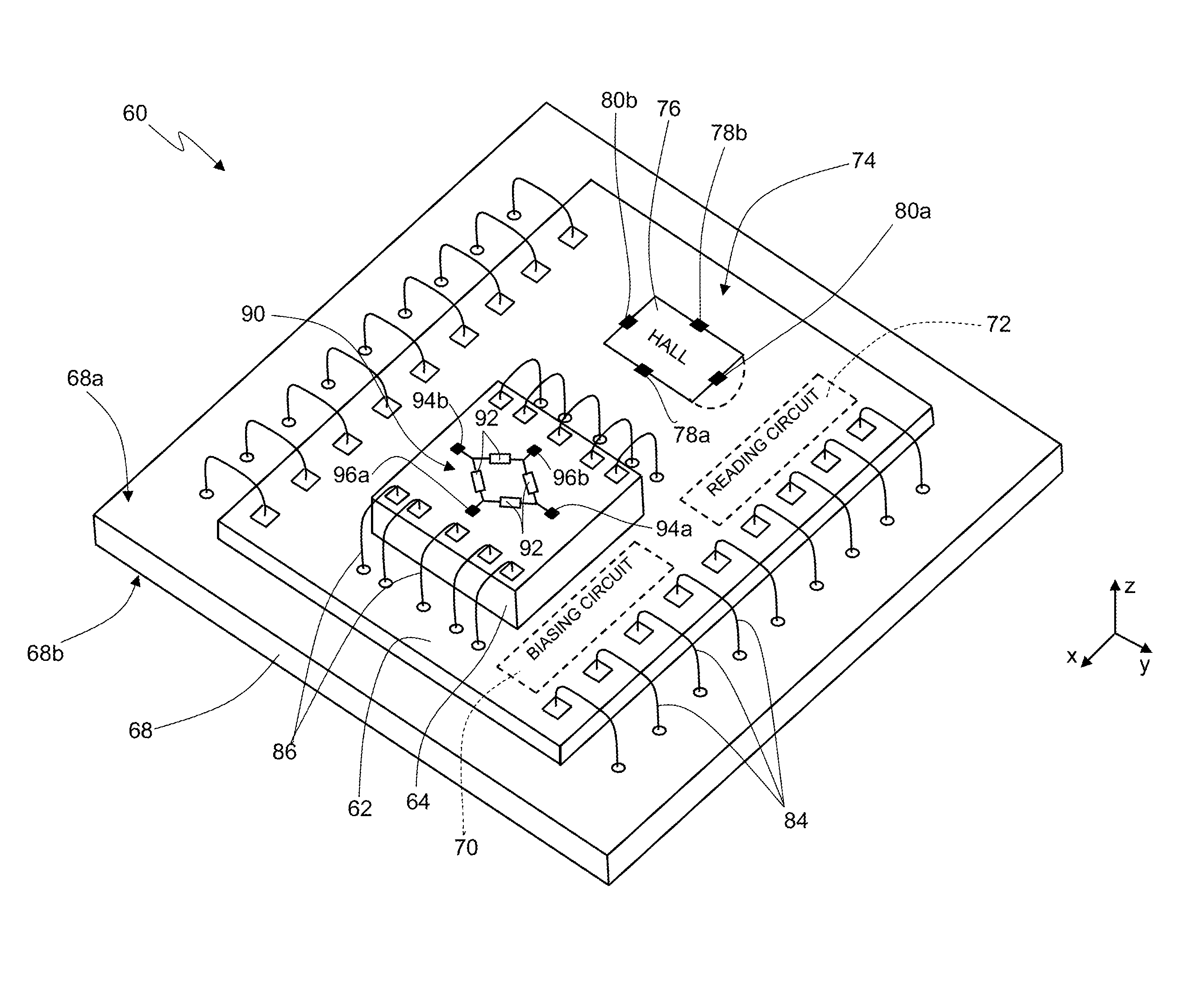
[0046]FIG. 4 shows a magnetic field sensor 60, which comprises a package (not shown), present inside which are a first die 62, a second die 64, and a support 68.

[0047]The support 68 has a top surface 68a and a bottom surface 68b, is made for example of organic resin, and includes vias and paths made of conductive material (not shown). In practice, the support 68 performs the function of carrying the first and second dice 62, 64, as well as the function of enabling electrical connection of the magnetic field sensor 60 with the outside world. For this purpose, the bottom surface 68b has a plurality of pads of conductive material, not shown.

[0048]In greater detail, formed within the first die 62 are an electronic supply circuit 70 and an electronic reading circuit 72, as well as a Hall transducer 74, i.e., a first electronic structure in itself known and designed to supply, when electrically supplied, a first electrical quantity that is a function of a possible first external magnetic ...


PUM


Abstract

A magnetic field sensor, including a Hall magnetic sensor, formed within a first die and configured to detect a first magnetic field, and a first anisotropic magnetoresistive magnetic sensor, having a first anisotropic magnetoresistive transducer, formed within a second die and configured to generate an electrical measurement quantity as a function of a second magnetic field. An electronic reading circuit formed within the first die, is electrically connected to the first anisotropic magnetoresistive transducer, and provides a first measure indicating the second magnetic field, on the basis of the electrical measurement quantity. The first and second dice are fixed with respect to one another and have main surfaces parallel to the same reference plane. The first magnetic field being oriented in a first direction perpendicular to the reference plane and the second magnetic field being oriented in a second direction parallel to the reference plane.

Description

BACKGROUND[0001]1. Technical Field[0002]The present disclosure relates to a magnetic field sensor; in particular, a magnetic field sensor including an anisotropic magnetoresistive (AMR) magnetic sensor and a Hall magnetic sensor.[0003]2. Description of the Related Art[0004]As is known, today available are numerous magnetic field sensors, also known, in brief, as “magnetic sensors”.[0005]Magnetic field sensors enable detection of natural magnetic fields (for example, the Earth's magnetic field) and magnetic fields generated by electrical components (such as electrical or electronic devices and lines traversed by electric current); i.e., they generate output signals indicating these magnetic fields.[0006]Magnetic field sensors are widely used in a vast range of applications. In particular, magnetic field sensors are today used within numerous systems, such as for example compasses, systems for detecting ferrous materials, systems for detecting currents, etc.[0007]In detail, there exis...

Claims


Application Information

Patent Timeline
Patent Type & Authority Applications(United States)
IPC IPC(8): G01R33/09H01L43/14G01R33/07
CPCG01R33/096G01R33/07G01R33/0206G01R33/0005H01L43/14H01L2224/48145H01L2224/48227H10N52/01
Inventor UNGARETTI, TOMMASOVIGNA, BENEDETTOBOTTINELLI, FABIO
Owner STMICROELECTRONICS SRL
Why Eureka
Try Eureka