Clock generator

a clock and loop technology, applied in the field of frequency locked loops, can solve the problems of high quality clock accompanying input data, increased output frequency, data gaps, etc., and achieve the effect of lower jitter and higher frequency accuracy

Active Publication Date: 2013-05-23
CIRRUS LOGIC INC
View PDF6 Cites 27 Cited by
  • Summary
  • Abstract
  • Description
  • Claims
  • Application Information

AI Technical Summary

Benefits of technology

[0020]wherein the first and second oscillators are configured such that the first oscillator clock signal has lower jitter than th

Problems solved by technology

Conversely, if the frequency of the output clock becomes lower than the desired frequency, a positive frequency error signal is generated, causing the output frequency to increase.
The clock accompanying the input data may not be high quality, due to either a poor quality clock source or degradation along the transmission channel, and the clock for signal processing may need to be a multiple

Method used


Image

  • Clock generator
  • Clock generator
  • Clock generator

Examples


Embodiment Construction

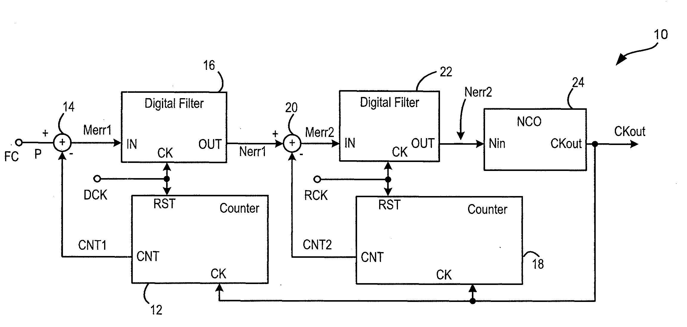
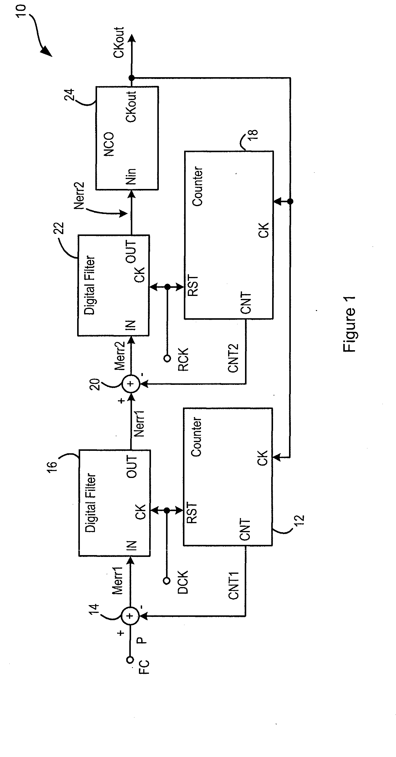
[0040]FIG. 1 shows a clock generator (or equivalently a frequency generator or frequency synthesiser) 10, which operates using the principles of a frequency locked loop. The clock generator 10 can for example be provided in the form of an integrated circuit, or it can be provided as a functional block as part of a larger integrated circuit. The clock generator 10 receives a first input clock signal DCK, having a frequency fDCK, and a second input clock signal RCK, having a frequency fRCK, and generates an output clock signal CKout, having a frequency fCKout. The clock generator 10 also receives, at a frequency control input FC, an input value or frequency control word P, which represents the desired value of the ratio of the frequencies of the output clock signal CKout and the first input clock signal DCK. Thus, where a user wishes to generate an output clock signal CKout having a frequency fCKout, and has a clock signal DCK at a frequency fDCK available, the value of P is set to be...


PUM


Abstract

A clock generator receives first and second clock signals, and input representing a desired frequency ratio. A comparison is made between frequencies of an output clock signal and the first clock signal, and a first error signal represents the difference between the desired frequency ratio and this comparison result. The first error signal is filtered. A comparison is made between frequencies of the output clock signal and the second clock signal, and a second error signal represents the difference between the filtered first error signal and this comparison result. The second error signal is filtered. A numerically controlled oscillator receives the filtered second error signal and generates an output clock signal. As a result, the output clock signal has the jitter characteristics of the first input clock signal over a useful range of jitter frequencies and the frequency accuracy of the second input clock signal.

Description

[0001]This application claims the benefit of U.S. Provisional Application No. 61 / 562,327, filed on Nov. 21, 2012, the disclosure of which is incorporated by reference.BACKGROUND OF THE INVENTION[0002]1. Field of the Invention[0003]This invention relates to a frequency locked loop, and in particular to a frequency locked loop suitable for use as a clock generator in integrated circuit form.[0004]2. Description of the Related Art[0005]It is known to use a frequency locked loop (FLL) to generate a clock signal at a frequency that is a multiple of the frequency of an existing (input) clock signal. For example, a high-frequency output clock clocks a counter. At edges of the existing clock signal, the accumulated count is latched and the counter is reset. Thus, the count represents the ratio of the frequency of the output clock to the frequency of the existing clock. This ratio is subtracted from an input value representing the desired ratio, and the resulting frequency error signal is fe...

Claims


Application Information

Patent Timeline
IPC IPC(8): H03L7/08H03G5/00
CPCH03L7/08H03G5/00H03L2207/50H03L7/14H03L7/18H03L7/087G06F3/162H03G5/005H03L7/099
Inventor LESSO, JOHN PAUL
Owner CIRRUS LOGIC INC
Why Eureka
Try Eureka