Foil bearing supported motor-driven blower

a technology of motor-driven blowers and bearings, which is applied in the field of turbomachinery, can solve the problems of large parasitic load in the system of air blowers, insufficient cooling of the internal components of the machine, and many prior art turbomachines designed to operate at high speeds, so as to reduce the number of parts, save energy, and reduce the effect of operation or efficiency

Inactive Publication Date: 2013-05-23
R & D DYNAMICS
View PDF23 Cites 28 Cited by
  • Summary
  • Abstract
  • Description
  • Claims
  • Application Information

AI Technical Summary

Benefits of technology

[0023]An advantage of the present invention is that there is no possibility of oil or lubricant contamination in the water vapor flow since the blower is oil-free.
[0024]Another advantage of the present invention is that heat generated by the blower is moved into the process gas flow, which is useful for energy savings.
[0025]Another advantage of the present invention is that the blower of the present invention is readily adaptable to various application and systems where gas and air, and in particular, dry process gas, must be moved and circulated.
[0026]Another advantage of the present invention is that the blower of the present invention can be mounted in a vertical or horizontal direction without affecting operation or efficiency.
[0027]Another advantage of the present invention is that the bearings can run cooler, which, in turn, allows the blower to run faster (i.e., at higher speeds).
[0028]Another advantage of the present invention is that the cooling scheme for the blower of the present invention reduces the number of parts in the blower, resulting in lower manufacturing costs, and permitting the blower to have a small size and comparatively light weight.

Problems solved by technology

However, in fuel cells, the largest parasitic load in the system is the air blower.
Heretofore, known problems with blowers generally arose due to the excessive size, weight, and complexity of such devices.
However, many prior art turbomachines designed to operate at high speeds have not adequately cooled the internal components of the machine, especially the bearings.
As a result, turbomachines operating at high speeds, without proper cooling methods, often experience low efficiency, low reliability, and a high risk of damage and over-heating.
Blowers using such conventional bearings typically run at low speeds and, as a result, occupy a large space and operate at low efficiency levels.
Conventional bearings have not been able to withstand high rotational speeds without increasing the complexity of the blower design.
Additionally, conventional bearings often require oil lubrication that can contaminate the blower and the fuel cell and result in damage, reduced efficiency and reduced reliability.
An overview of foil air bearing technology is provided in an ASME paper (97-GT-347) by Gin L. Agrawal. However, even use of foil bearings in blowers have not automatically translated into higher efficiency and reliability of the machines.
Fully addressing the high temperatures associated with high speed operation has still proven difficult for prior art blower designs.
However, as the internal components can generate high temperatures during operation, especially at high operating rotational speeds, isolating the internal components of the blowers often requires a separate lubrication and cooling system to be incorporated into the blower design to prevent damage and failure of the blower.
Accordingly, sealing the rotating parts from the process gas while permitting a separate coolant flow through the blower housing requires a more complex design than for typical blowers.
Moreover, leakage from the lubricant or coolant for the blower's rotating parts may cause contamination of the process gas, and vice versa.
In addition to the disadvantages presented by the issues of leakage and contamination within a blower, the isolation of the motor and other internal blower parts from the process gas makes it difficult to adequately contain the heat that is generated by these parts during operation of the blower.
The heat is lost to the environment, which affects the efficiency of the system.
To contain the heat using prior art blower designs, an additional system is needed to collect and manage the heat, which adds to the complexity, size, weight and cost of the system.
However, some designs that use axial fans or rotating impellers, such as U.S. Pat. Nos. 7,855,882 and 8,016,574 do not adequately cool the bearings and other internal components, and as noted above, such systems are not acceptable for blowers operating at high speeds.

Method used


Image

  • Foil bearing supported motor-driven blower
  • Foil bearing supported motor-driven blower
  • Foil bearing supported motor-driven blower

Examples


Embodiment Construction

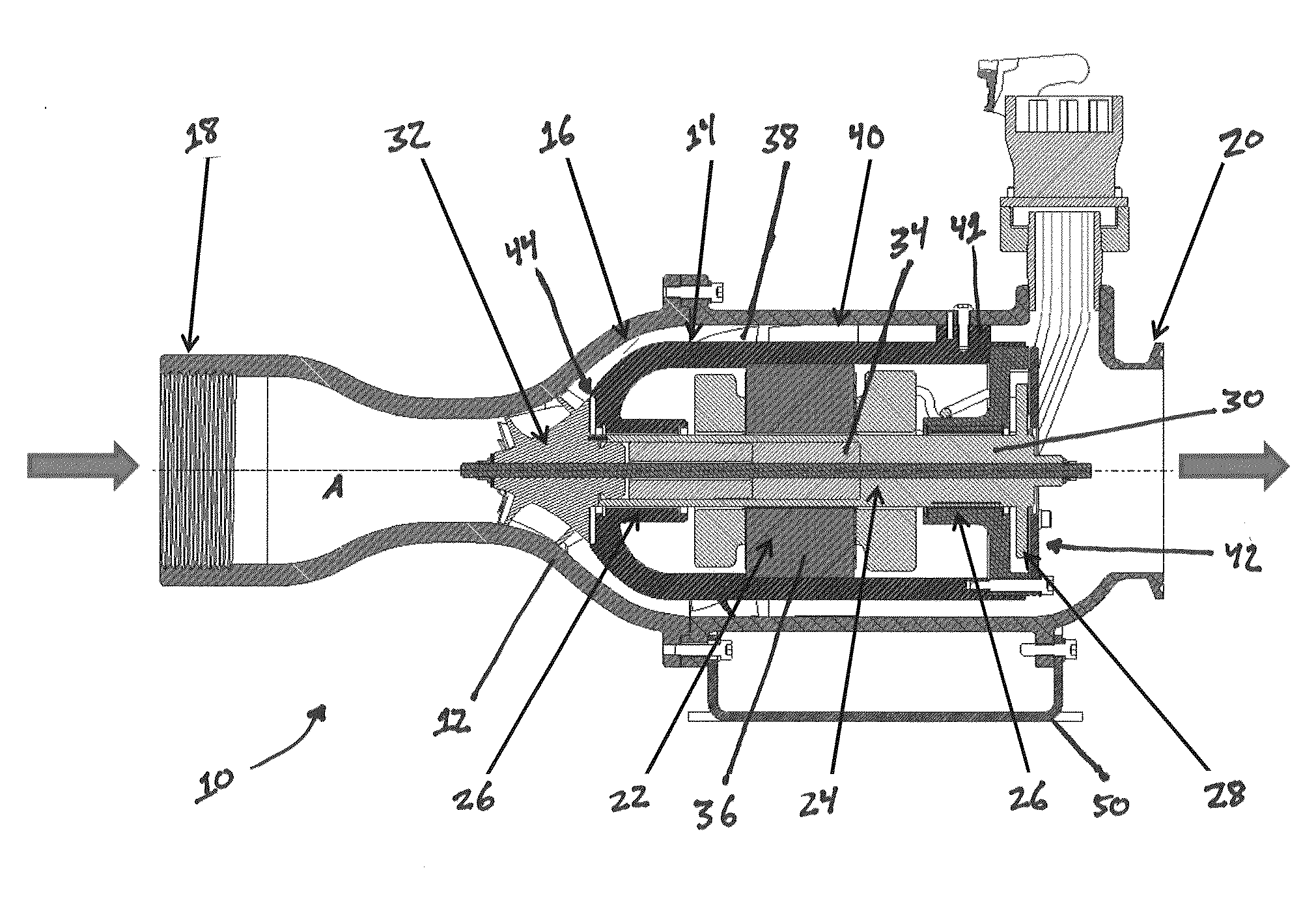
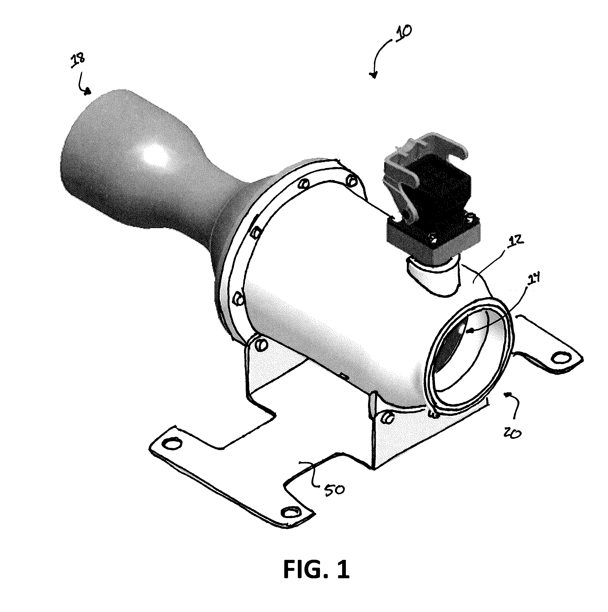
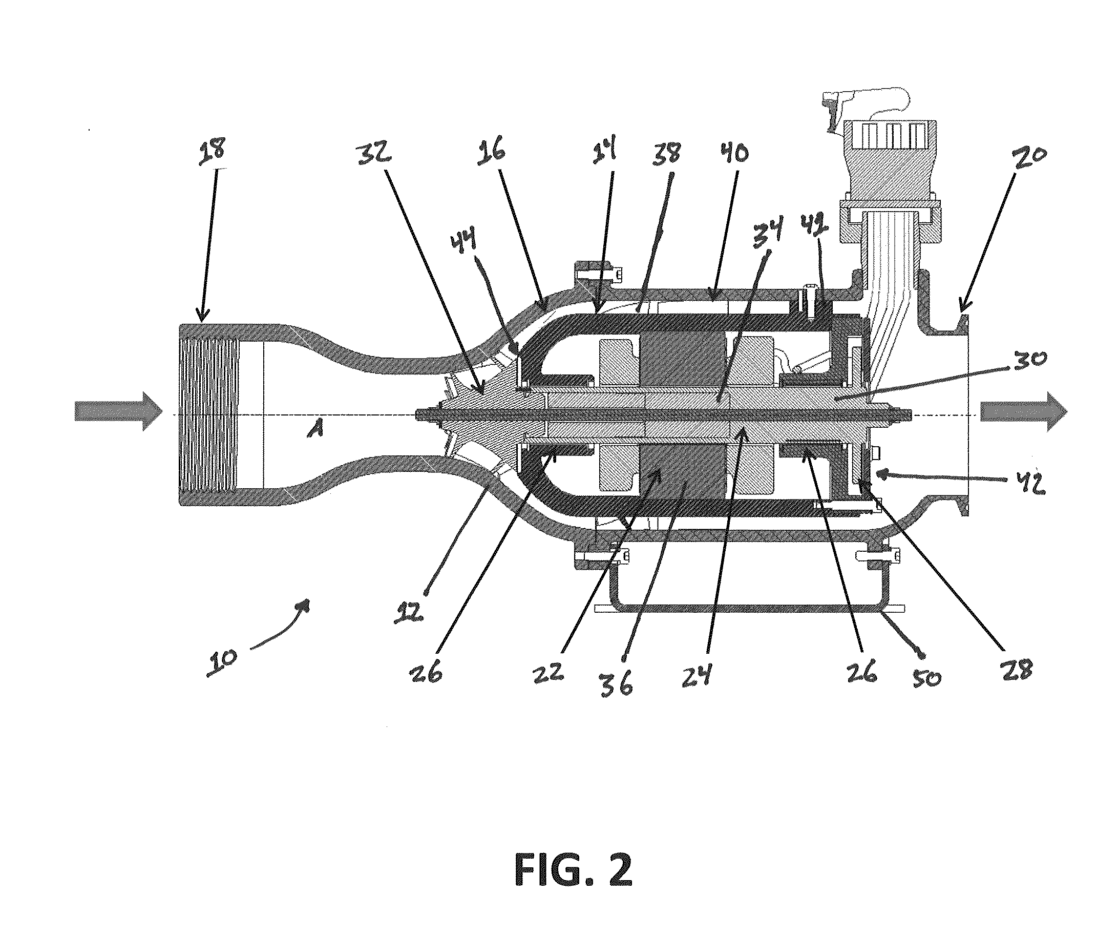
[0038]The present invention is directed to a motor-driven blower for movement, circulation and compression of gas and air, preferably a dry process gas. More preferably, the present invention is directed to a high-speed, single-stage, motor-driven blower. A perspective view and a cross-sectional view of an exemplary blower in accordance with the present invention, generally designated by reference numeral 10, are illustrated in FIGS. 1 and 2.

[0039]The blower 10 of the present invention is preferably a small, high-efficiency, oil-free device that can be used in various applications, such as for fuel cell air management (both in stationary and mobile designs), and for aeration units, printing systems and air knifes.

[0040]Referring to FIG. 2, a cross-sectional view of a blower 10 in accordance with the present invention showing internal components thereof is provided. As shown, the blower 10 comprises an outer housing 12 and an inner housing 14 disposed therein to define an annular cav...


PUM


Abstract

A high-speed blower designed to move and circulate dry process gas includes an axial or mixed-flow compressor driven by a brushless permanent magnet synchronous motor utilizing a remotely mounted variable frequency drive. The blower uses foil gas bearings which enable high-speed, low-power loss, and oil-free operation. The blower comprises an outer blower housing and an inner blower housing defining an annular cavity therebetween. A cooling flow of process gas may be leaked through the inner blower housing to cool the internal operational components of the blower, including the motor and the bearings, and to capture heat therefrom, which can be added to the process gas flow moving through the blower. Diffuser vanes and flow-straightening vanes are provided on the outer surface of the inner blower housing to improve the fluid dynamics of the process gas flow through the blower and heat transfer from the inner blower housing.

Description

CROSS-REFERENCE TO RELATED APPLICATION[0001]This application claims the benefit of U.S. Provisional Application No. 61 / 561,443, filed Nov. 18, 2011, which is incorporated herein by reference.FIELD OF THE INVENTION[0002]The present invention relates generally to the conception, design and manufacture of turbomachinery, such as blowers. More particularly, the present invention relates to a blower designed for movement of gas, especially dry gas, that has high efficiency, high reliability, and a small size and weight. The present invention also relates to a fuel cell system incorporating a motor-driven blower designed to move and circulate dry gas.BACKGROUND OF THE INVENTION[0003]All fuel cells require air or gas to be supplied to the cathode side of the fuel cell for proper operation. Movement of air or gas to the cathode side of a fuel cell is typically accomplished using a blower. However, in fuel cells, the largest parasitic load in the system is the air blower. Thus any improvemen...

Claims


Application Information

Patent Timeline
Patent Type & Authority Applications(United States)
IPC IPC(8): F04D29/057
CPCF04D29/057F04D29/542F04D25/082F04D17/06F04D29/5853F05D2250/52F04D29/444F04D29/5806
Inventor AGRAWAL, GIRIDHARI L.BUCKLEY, CHARLES W.NELSON, ALEXANDER R.
Owner R & D DYNAMICS
Why Eureka
Try Eureka