Computer program for spine mobility simulation and spine simulation method

a computer program and spine technology, applied in medical simulation, image data processing, sensors, etc., can solve the problems of increasing the stress on adjacent spinal motion segments, predisposing neighboring spinal motion segments to rapid deterioration, and lack of mobility,

Inactive Publication Date: 2013-05-23
SPONTECH MEDICAL AG
View PDF1 Cites 64 Cited by
  • Summary
  • Abstract
  • Description
  • Claims
  • Application Information

AI Technical Summary

Benefits of technology

[0014]It is therefore an object of the present invention to provide means that assist the surgeon in determining a configuration of a spine implant which is most suited for being implanted into the patient.

Problems solved by technology

Spinal fusion procedures, however, have raised concerns in the medical community that the bio-mechanical rigidity of intervertebral fusion may predispose neighboring spinal motion segments to rapid deterioration.
Such lack of mobility tends to increase stresses on adjacent spinal motion segments.
However, it has turned out that even if prostheses allowing pivotal and rotational movements are used, the results of the implant surgery are still often unsatisfactory.
The present inventors have discovered that in many cases this is due to the fact that the implants do not allow for the specific needs of the individual patient.
More particularly, the conventional approaches fail to exactly restore the required mobility of the affected vertebrae, and they also ignore the natural mobility range of the adjacent vertebrae in the respective spine segment which usually differs from patient to patient.
For example, wrong tapering angles inevitably lead to more stress than necessary on adjacent joints.
A wrong cage length may cause a cage to sink, at some time after the surgery, into the soft bone tissue of the vertebrae that is surrounded by a harder bone ring.
As a matter or course, the problem of determining the optimum implant configuration also occurs if adjustable cages are used.
However, it is difficult for a surgeon to determine the optimum fusion cage or the optimum configuration of a prosthesis solely on the basis of experience and certain biometrical data which he has obtained for the relevant spine segment, for example using medical imaging techniques.

Method used


Image

  • Computer program for spine mobility simulation and spine simulation method
  • Computer program for spine mobility simulation and spine simulation method
  • Computer program for spine mobility simulation and spine simulation method

Examples


Embodiment Construction

[0122]1. Introduction

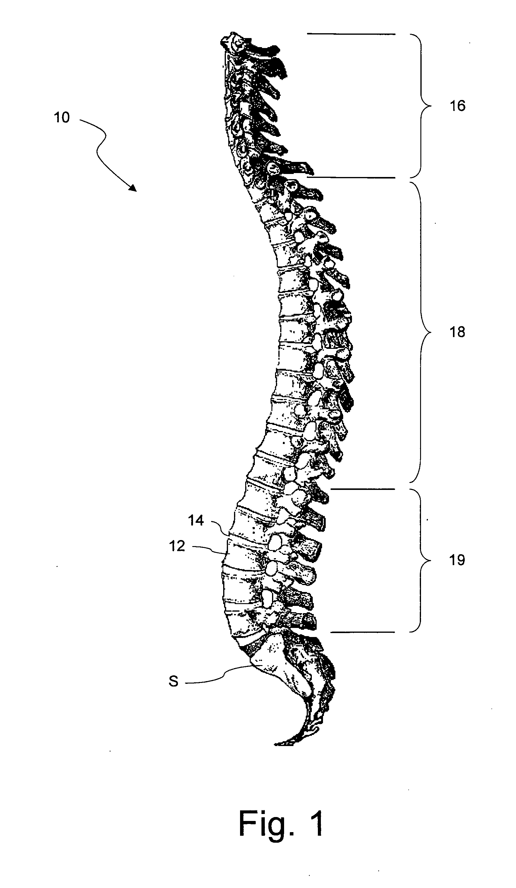
[0123]FIG. 1 is a side view of a human spine comprising vertebrae 12 and intervertebral disks 14 which are arranged in intervertebral disk compartments formed between adjacent vertebrae 12. The first seven vertebrae 12 of the spine 10, counted from its top, form the cervical spinal column 16, the following twelve vertebrae the thoracic spinal column 18, and the remaining five vertebrae 12 the lumbar spinal column 19. The latter is connected by the sacrum S to the pelvic. The cervical and lumbar spinal columns 16, 19 have a lordotic curvature, whereas the thoracic spinal column 18 has a kyphotic curvature. From FIG. 1 it becomes clear that the vertebrae 12 and also the intervertebral disks 14 have different shapes and sizes. This, in turn, results in the different curvatures and also in different mobilities of the spinal segments. Thus the joints formed by pairs of adjacent vertebrae 12 have properties that significantly differ along the spinal column.
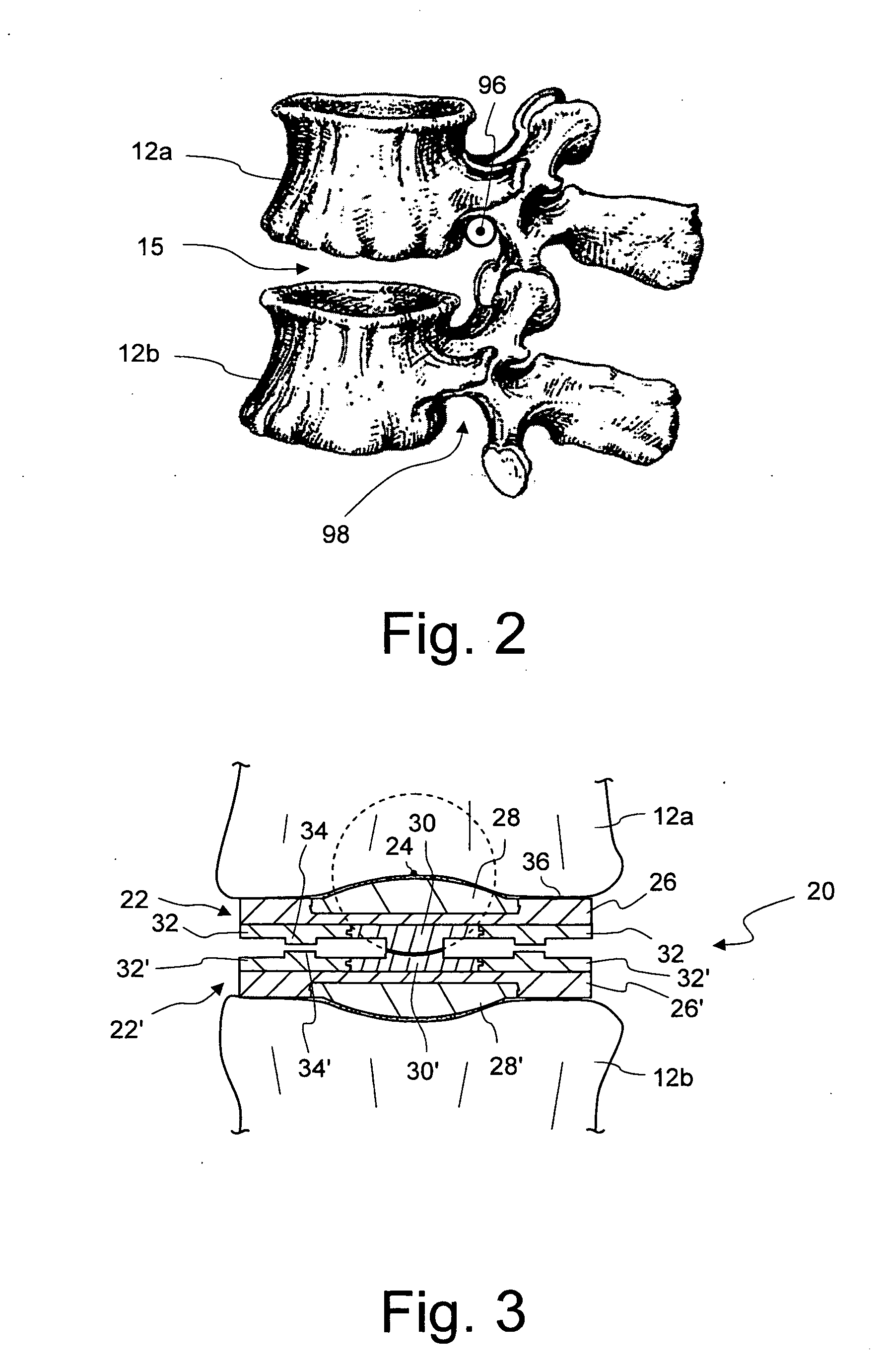
[0124]FIG. ...


PUM


Abstract

A computer program for spine mobility simulation is configured, if running on a computer, to cause the computer to perform the following steps: a) accessing bio-metric data which relate to the spine of a patient, the spine having at least one compromised spine segment; b) displaying a model of the spine of the patient comprising a plurality of vertebrae; c) enabling a user to change the position of at least one of the vertebrae of the spine model; d) computing the effects of the position change on the remaining vertebrae; e) displaying the spine model in a new configuration, thereby taking into account the position changed by the user in step c) and the position changes of the remaining vertebrae computed in step d).

Description

BACKGROUND OF THE INVENTION[0001]1. Field of the Invention[0002]The present invention relates to a computer program for spine mobility simulation. Such a program may be used for configuring a spine implant, for example a cage or another fusion implant, or a non-fusion implant such as an intervertebral disk prosthesis. The present invention also relates to a spine simulation method.[0003]2. Description of Related Art[0004]In the treatment of diseases, injuries or malformations affecting spinal motion segments, and especially those affecting disk tissue, it has long been known to remove some or all of a degenerated, ruptured or otherwise failing disk. In cases involving intervertebral disk tissue that has been removed or is otherwise absent from a spinal motion segment, corrective measures are indicated to ensure the proper spacing of the vertebrae formally separated by the removed disk tissue.[0005]Sometimes the two adjacent vertebrae are fused together using transplanted bone tissue...

Claims


Application Information

Patent Timeline
Patent Type & Authority Applications(United States)
IPC IPC(8): A61B5/107
CPCA61F2/30744A61B5/1079A61F2/4425A61F2/4455A61F2/4611A61F2002/30604A61F2002/30616A61F2002/3085A61F2002/30948G06F19/3437G06T19/20G06T2210/41G06T2219/2004G09B23/30A61F2/30942G16H50/50
Inventor COPF, FRANZWELSCH, NORBERTWELSCH, THOMASLOUVARD, ERICHANISCH, FRANKPROSS, GERHARDSCHOLS, ERIK
Owner SPONTECH MEDICAL AG
Why Eureka
Try Eureka