
Intravenous infiltration detection

Inactive Publication Date: 2013-05-23
PHOENIX CHILDRENS HOSPITAL
View PDF9 Cites 9 Cited by
  • Summary
  • Abstract
  • Description
  • Claims
  • Application Information

AI Technical Summary

Benefits of technology

The technical effects of this patent text are to provide a method and apparatus for detecting IV infiltration or extravasation without direct heating or cooling of the therapeutically administered biological fluid or tissue near the injection site. The goal is to reduce harm to the patient and improve safety by detecting potential harm caused by infiltration or extravasation in a timely manner.

Problems solved by technology

At times, and due to various causes, the IV fluid infiltrates nonvascular tissue proximate to the site of injection or infusion, adversely affecting the surrounding tissue and disrupting the therapeutic schedule.
The IV solution can accumulate in the skin and subcutaneous tissue, possibly damaging the skin and tissues and preventing critical medication and / or nutrients from reaching the venous system.
Thus, several complications can result from an infiltration, including extravasation, tissue necrosis, phlebitis, venous inflammation, reduced therapy delivery and others.
Such infiltrations are difficult to detect, especially at an early stage of infiltration.
To date, these clinical methods for attempting to detect extravasations have proven to be unreliable, especially at an early stage of infiltration and in young children where there can be large dressings around the IV site to protect the IV from the child but which would interfere with visual and tactile examination.
Further, these clinical methods are often in error with infiltrations that are in progress or are moderately symptomatic.
So far these nonclinical methods have been largely unsuccessful.
Systems using such devices have not proven their usefulness and as a result are not in widespread use.
In particular, these latter techniques have not been found to be useful detection devices for early stage infiltrations because the changes required by these devices require substantial amounts of infiltrate or tissue reaction.
This patent recognizes that in clinical situations, the injected fluid temperature and the tissue temperature at the site of injection may be very close, preventing an accurate assessment of infiltration.
The overall system is highly complex in nature, requiring sophisticated device elements.
Obviously, this system is only operable if the fluid being injected is of sufficient temperature difference from the tissue at the point of injection.

Method used


Image

  • Intravenous infiltration detection
  • Intravenous infiltration detection
  • Intravenous infiltration detection

Examples


Embodiment Construction

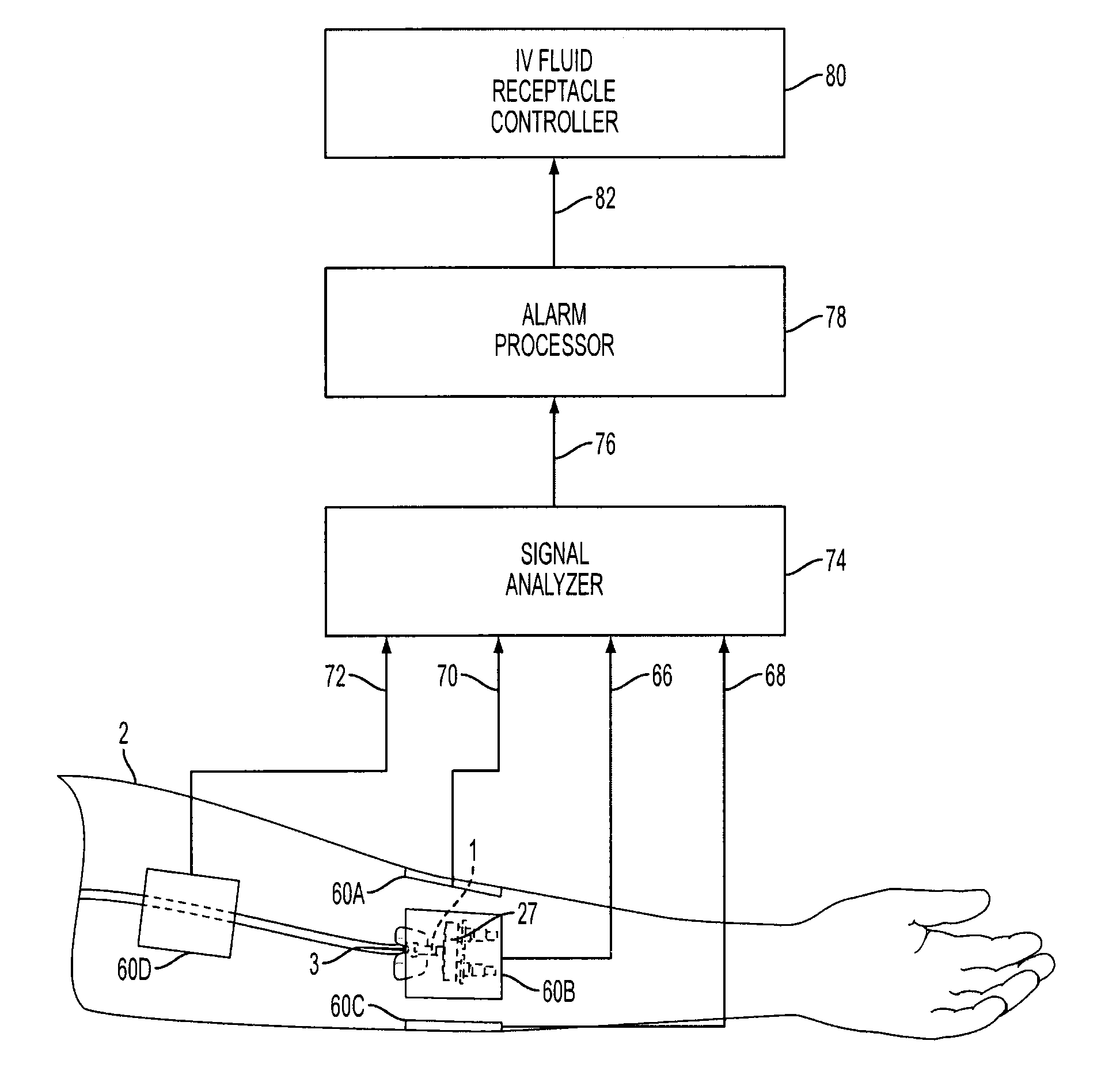
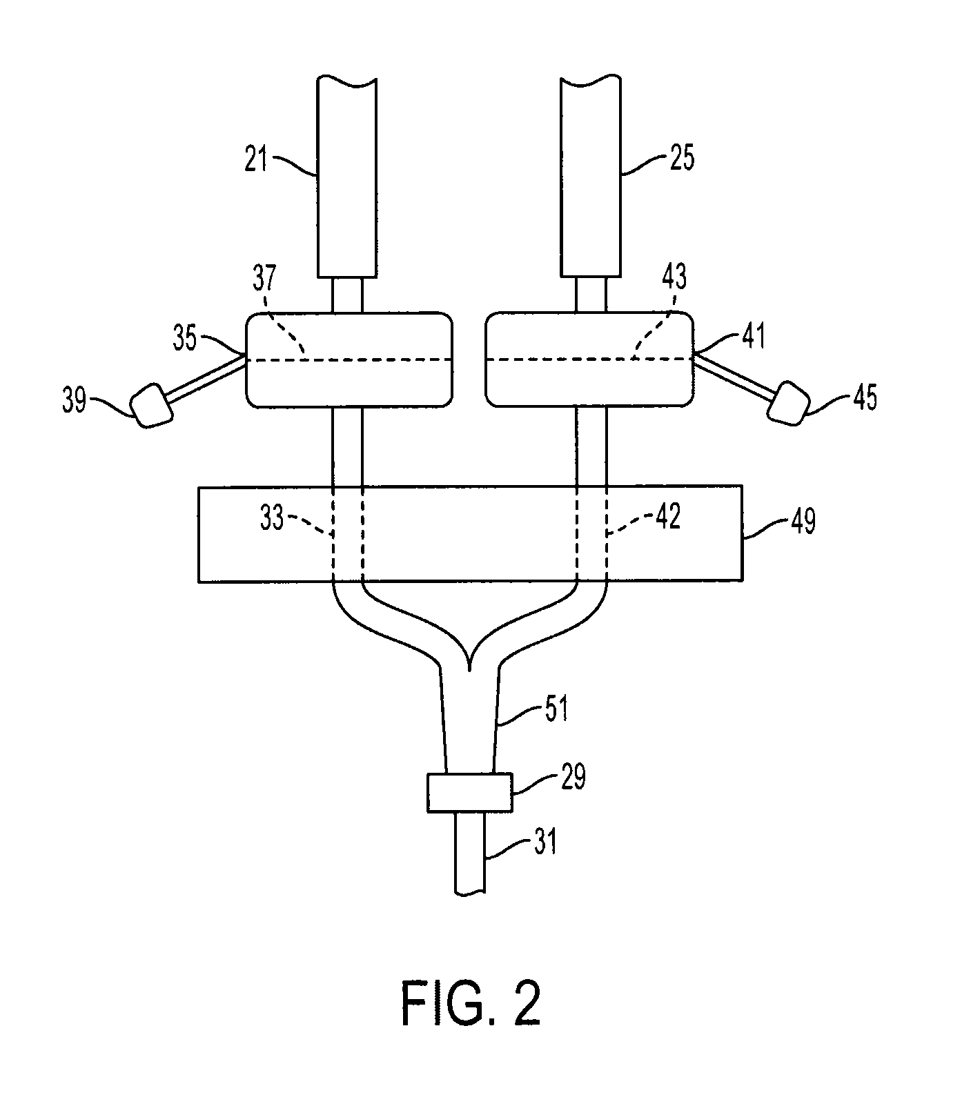
[0032]The present invention provides a method and means for allowing medical personnel to detect the occurrence of an infiltration or extravasation during intravenous (IV) infusion in a clinical setting. IV infusion is a standard and often preferred method for administering therapeutic agents and nutrients directly into the blood stream of a patient. Herein, the term “therapeutic agent” is inclusive of all medicinal and nutritional substances which are administered via IV infusion in a continuous manner to a patient, as opposed to substances which are administered in a single injectable bolus. Of course, the IV infusion need not contain a therapeutic agent. The IV administerable therapeutic agent, for example, is inclusive of continuously administered anesthetics, continuously administered diagnostic agents such as contrast agents, continuously administered antibiotics and other drugs, continuously administered vitamins and other nutrients which at times are considered drugs, and th...


PUM


Abstract

A process and apparatus system for detecting an intravenous infiltration. A separate infiltration detecting solution containing an intravenously administerable infiltration indicator is intravenously administered singly or on a periodic basis and a qualitative and / or quantitative assessment of the indicator in tissue proximate and / or distal to the site of intravenous administration of a biological fluid is carried out.

Description

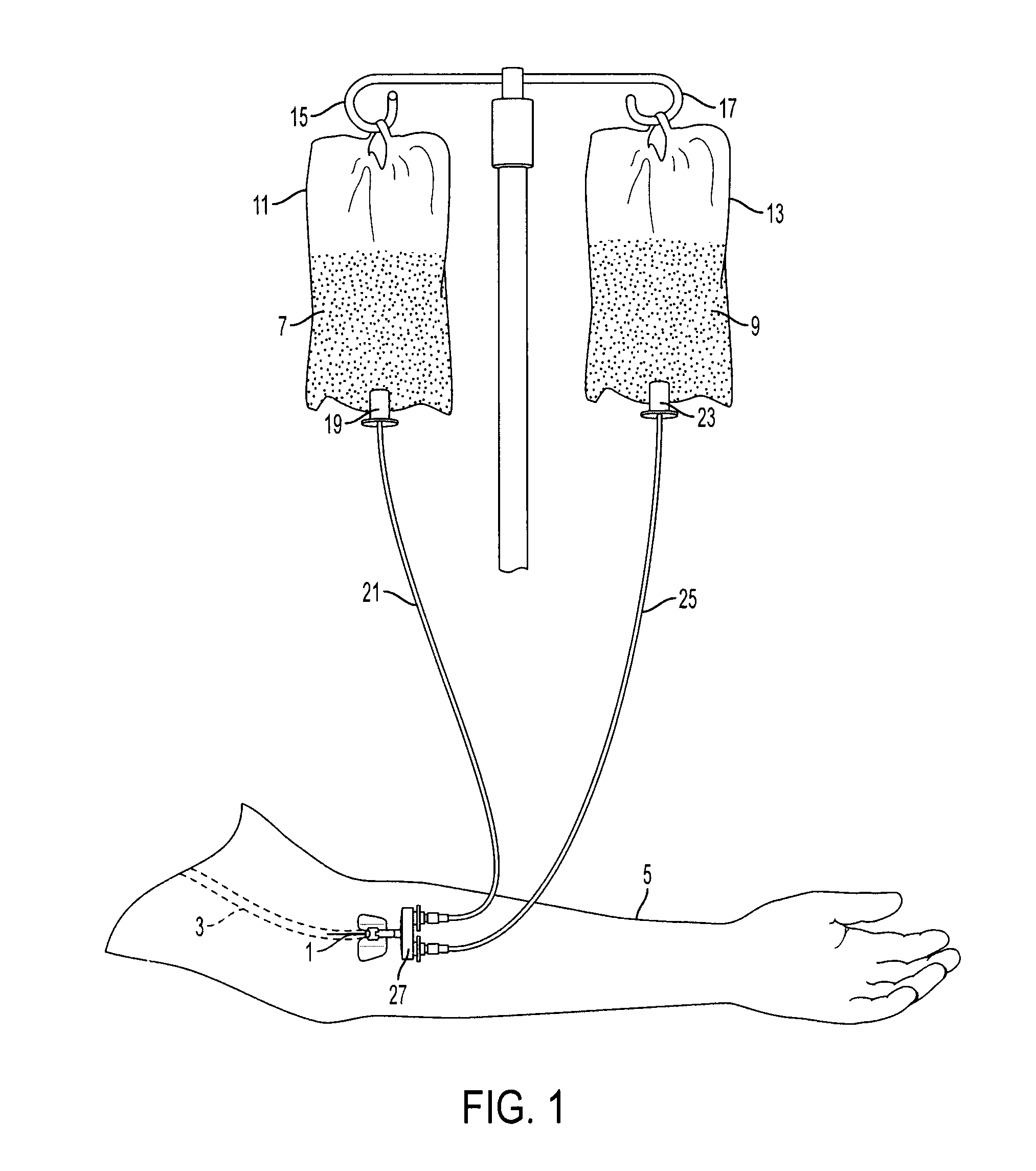
BACKGROUND OF THE INVENTION[0001]Intravenous (IV) infusion as a delivery means of a biological fluid to a patient is a common clinical procedure in medical settings. In the United States, approximately 80% of hospitalized patients receive IV therapy. In general, a needle or cannula is inserted into a peripheral vein and connected to an IV bag containing a biological fluid by means of a flexible connector tube. The biological fluid can be mere saline solution and / or contain any of the numerous therapeutic agents and / or nutrients administerable by IV infusion.[0002]At times, and due to various causes, the IV fluid infiltrates nonvascular tissue proximate to the site of injection or infusion, adversely affecting the surrounding tissue and disrupting the therapeutic schedule. Further, the infiltration can permeate tissue distal to the site of IV infusion, such as in the vicinity of the venous drainage system of the IV infusion. The IV solution can accumulate in the skin and subcutaneous...

Claims


Application Information

Patent Timeline
IPC IPC(8): A61B6/00A61B5/01
CPCA61M2205/18A61M5/158A61M5/1408A61M2005/1588
Inventor POLLACK, MURRAY M.
Owner PHOENIX CHILDRENS HOSPITAL
Learn More