Cast Iron Pipe Cutter

a cutting machine and cutter technology, applied in the field of cast iron pipe cutters, can solve the problems of low tensile strength, low ductility, brittleness, etc., and achieve the effects of reducing time, ensuring the ability to create straighter clean cuts, and ensuring the safety of the operator/user

Inactive Publication Date: 2021-12-02
DENHERDER SCOTT +1
View PDF8 Cites 0 Cited by
  • Summary
  • Abstract
  • Description
  • Claims
  • Application Information

AI Technical Summary

Benefits of technology

[0007]The present invention is a cast iron pipe cutter capable of consistently creating straight clean cuts in a variety of cast iron pipes in minimal time. The cast iron pipe cutter of the present invention is further capable of cutting different size cast iron pipes while maintaining the ability to create straighter clean cuts. Further, the cast iron pipe cutter requires minimal effort from the user to operate, creating a much safer environment for the operator / user. The straight clean cuts created by the cast iron pipe cutter are consistent, repeatable, and mechanical. As a result, the cast iron pipe cutter of the present invention is optimal for factory use, enabling precutting of cast iron pipe to specified lengths thereby eliminating the need to make cuts in the field.

Problems solved by technology

However, cast irons have low tensile strength, low ductility, and are brittle.
Also, due to the toughness and hardness of cast irons, cutting cast iron pipe with traditional cutting equipment is time consuming.
The wear and tear on traditional cutting equipment also makes it costly as blades and cutting discs quickly wear.
Additionally, cutting cast iron pipes at a work site with traditional cutting equipment increases the cost of a project by using valuable work and equipment time.
Due to the low ductility, brittleness, and non-malleable nature of cast iron pipes, the applied pressure fractures and snaps the pipe.
Although the chain pipe cutter decreases cutting time compared to traditional cutting equipment, the chain pipe cutter still has disadvantages.
By utilizing the same chain assembly for multiple diameters of pipe, the chain piper cutter cannot make clean straight cuts for all pipe diameters.
Chain pipe cutters are susceptible to oblique cuts with rough edges.
Additionally, the chain pipe cutters occasionally destroy the cast iron pipes being cut creating waste and taking up more valuable work hours to replace or repair the broken cast iron pipe.
Chain pipe cutters are bulky and require significant clearance area for use at a work site and still require a significant time from set up to making a cut.
In addition, use of traditional chain pipe cutters requires the worker to strain and pull leverage, exposing the user to possible injury.

Method used


Image

  • Cast Iron Pipe Cutter
  • Cast Iron Pipe Cutter
  • Cast Iron Pipe Cutter

Examples


Embodiment Construction

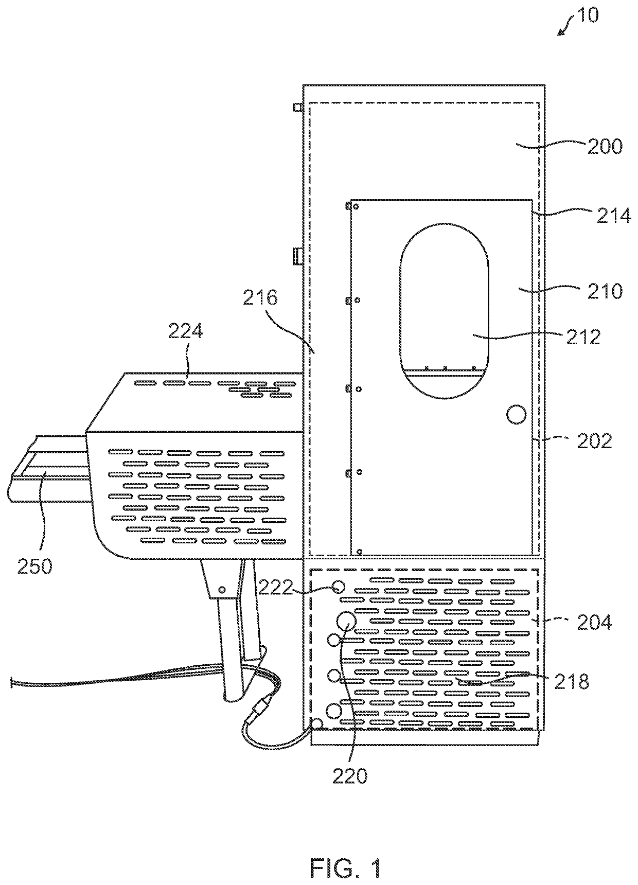
[0039]Referring initially to FIG. 1, a perspective view of a cast iron pipe cutter of the present invention is shown and generally designated 10. The cast iron pipe cutter 10 takes advantage of the physical properties of cast iron to make straight clean cuts quickly and consistently. Generally, the microcrystalline structures of different cast irons include a precipitate of carbon as a flake or spherical nodule surrounded by an iron matrix. The precipitate of carbon, such as graphite or carbide, present in the iron matrix creates localized spots in the cast iron that tend to form fractures. The cast iron pipe cutter 10 applies pressure on the exterior of the cast iron pipe to promote the formation of these fractures. By creating multiple fractures simultaneously at specific locations and forming subsequent fractures sequentially along the exterior of the cast iron pipe, the fractures develop and grow at a controlled rate and in a controlled direction. The multiple fractures amalgama...


PUM

PropertyMeasurementUnit
diametersaaaaaaaaaa
diameteraaaaaaaaaa
diameteraaaaaaaaaa

Abstract

The present invention is a cast iron pipe cutter. The cast iron pipe cutter includes a movable upper cutting tool and a rigid lower cutting tool. The upper cutting tool and lower cutting tool includes multiple cutting disc spaced an arc length apart. As the upper cutting tool is advanced downward by a hydraulic press, the cutting discs apply increasing pressure to the outer surface of a cast iron pipe until each cutting discs in the upper cutting tool and the lower cutting tool creates a fracture in the cast iron pipe. The multiple fractures created by the cutting discs amalgamate into a single fracture and the cast iron pipe is cut almost instantaneously.

Description

[0001]The present invention relates generally to cutting equipment. The present invention relates particularly, though not exclusively, to cast iron cutting equipment. The present invention is, though not exclusively, a cast iron pipe cutter. The present application claims priority to Provisional Patent Application No. 63 / 032,242, filed on May 29, 2020.FIELD OF INVENTIONBackground of the Invention[0002]Cast irons are a group of iron alloys with carbon content generally in the range of 2% to 4%. The higher carbon content of cast iron results in a heterogeneous alloy with more than one microcrystalline structure present in the material. Due to its unique microcrystalline structure, cast iron has unique physical properties. Generally, cast irons have high compressive strength, high hardness, high toughness, resistance to deformation, resistance to oxidation, resistance to wear, and a low melting point. The low melting point and high carbon content provides the molten form of cast irons...

Claims


Application Information

Patent Timeline
Patent Type & Authority Applications(United States)
IPC IPC(8): B26D3/16B26D1/00B26D1/03B26D1/09
CPCB26D3/16B26D1/0006B26D2001/006B26D1/09B26D1/03B26D1/06B26D2001/0053B26D2001/002B26D5/12B23D21/00B23D35/001B23D31/002
Inventor DENHERDER, SCOTTLUNDGREN, MARC
Owner DENHERDER SCOTT
Why Eureka
Try Eureka