Method of joining part having high fatigue strength

a technology of fatigue strength and jointing part, which is applied in the field of joining parts, can solve the problems of thermal stress in the object, reduce the yield stress of steel materials, and bring residual stress, and achieve high fatigue strength, high reliability, and high fatigue strength

Active Publication Date: 2013-05-30
OHASHI TECHNICA
View PDF0 Cites 8 Cited by
  • Summary
  • Abstract
  • Description
  • Claims
  • Application Information

AI Technical Summary

Benefits of technology

[0030]According to a method of joining a part having high fatigue strength of the present invention, a configuration is employed, in which a steel material that causes martensitic transformation is used for one of or both of a first member and a second member, a supporting electrode having a cooling circuit formed inside and a pressure electrode are used, the first member and the second member are subjected to solid-phase diffusion joining, the both members are rapidly cooled by thermal conduction of the supporting electrode after the joining, and quenching is performed to the joined portion. Therefore, compressive residual stress is caused in the joined portion of the first member and the second member, and a joined part having high fatigue strength can be obtained. Additionally, the joined portion has high reliability, and the joined part can be expeditiously and efficiently obtained. Therefore, effect of excellent economical efficiency can also be obtained.
[0031]According to a method of joining a part having high fatigue strength of the present invention, a configuration is employed, in which a steel material is used

Problems solved by technology

However, in a case where only a portion to be welded is locally heated like welding, the expansion is obstructed by surrounding materials, and this causes thermal stress in the object and brings about residual stress.
However, thermal deformation of expansion/constriction caused thereby is restricted by a surrounding base material, and yield stress of a steel material decreases with temperature, and plastic deforma

Method used


Image

  • Method of joining part having high fatigue strength
  • Method of joining part having high fatigue strength
  • Method of joining part having high fatigue strength

Examples


first embodiment

[0044]First, a joining method will be described.

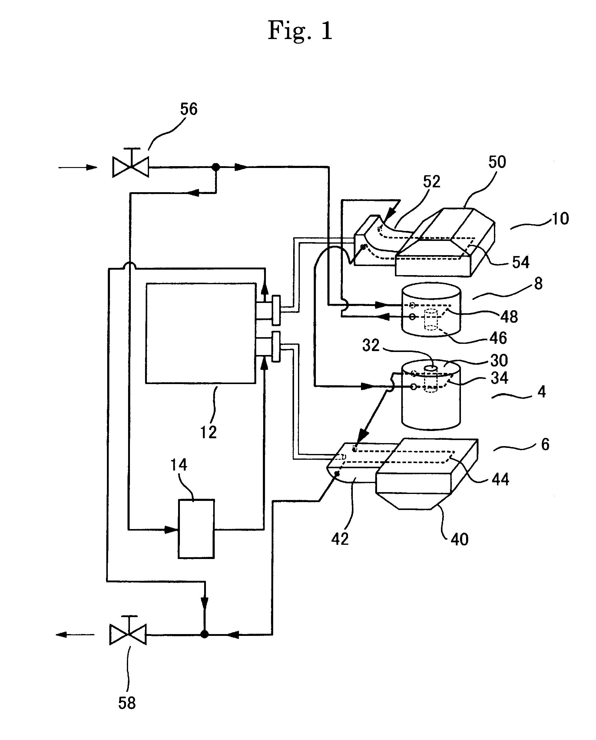
[0045]FIG. 1 illustrates a cooling system diagram of an electrode mechanism of a joining device for performing a method of joining a part having high fatigue strength according to an embodiment.

[0046]This electrode mechanism includes a supporting electrode 4, a lower platen 6 that holds the supporting electrode 4, a pressure electrode 8, an upper platen 10 that holds the pressure electrode 8, a power transformer 12 (TR) for power supply, a thyristor 14 (SCR) that controls cut-off of power supply to the electrode, and the like. Further, the above-described joining device includes a positioning mechanism, a pressure mechanism (not illustrated), and the like.

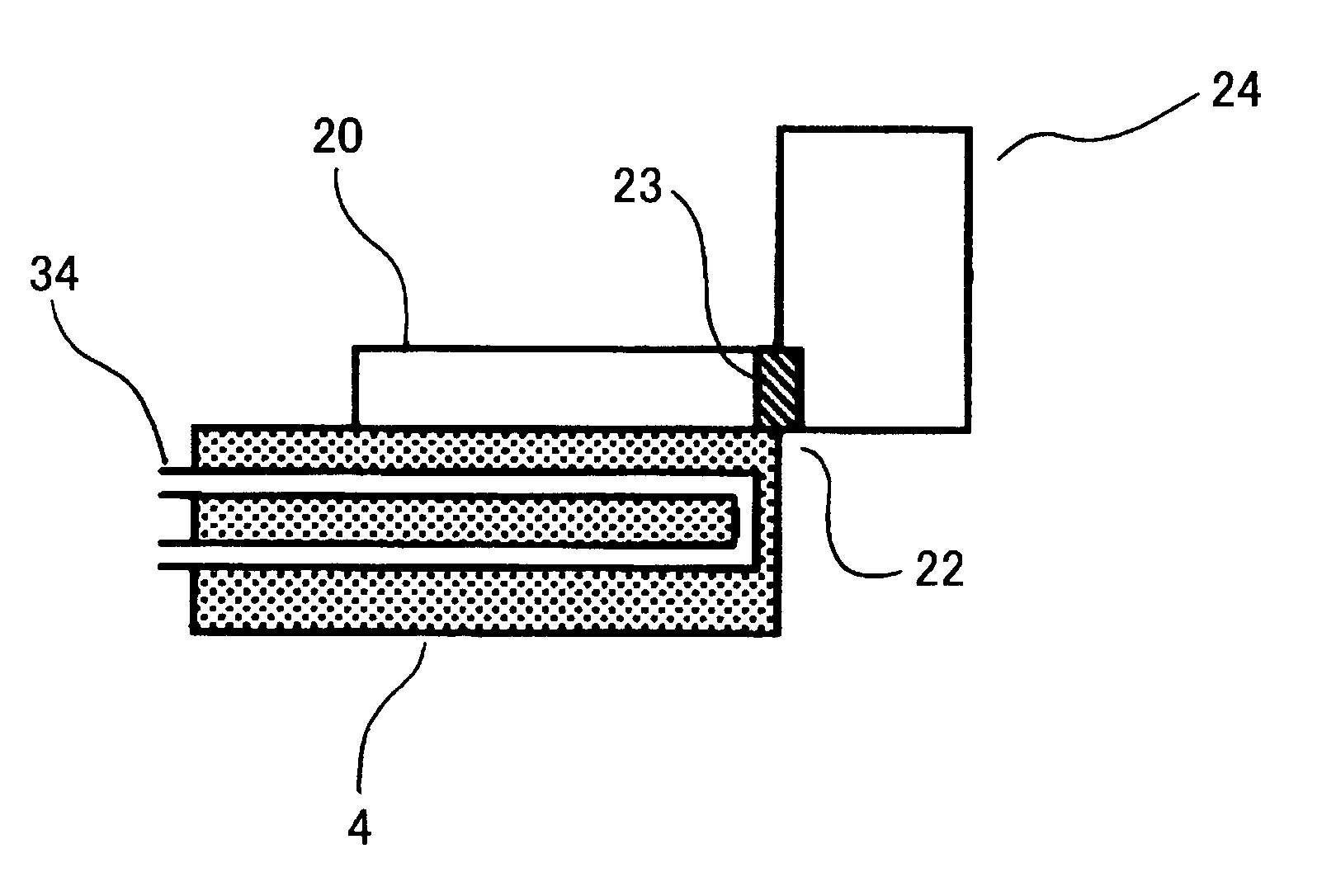
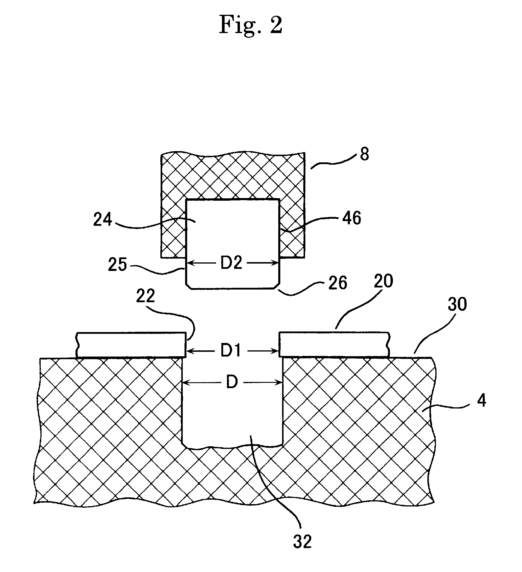
[0047]As illustrated in FIG. 2, a part to be joined by the joining device is formed of an element part made of metal, and includes a plate member 20 provided with an opening portion 22 and a shaft member 24 joined to the opening portion 22 of the plate member.

[0048]Both of the suppor...

second embodiment

[0146]Next, a joining method will be described.

[0147]FIG. 6 illustrates a cooling system diagram of an electrode mechanism of a joining device for performing a method of joining a part having high fatigue strength according to an embodiment.

[0148]Here, jigs, members, and the like related to this embodiment that are equivalent to those of the first embodiment will be provided with the same reference signs and detailed description will not be repeated.

[0149]This electrode mechanism includes a supporting electrode 4, a lower platen 6 that holds the supporting electrode 4, a pressure electrode 8, an upper platen 10 that holds the pressure electrode 8, a power transformer 12 (TR) for power supply, a thyristor 14 (SCR) that controls cut off of the power supply to an electrode, and the like. Further, the joining device includes a positioning mechanism, a pressure mechanism (not illustrated), and the like.

[0150]A part to be joined by the joining device is formed of an element part made of ...


PUM

PropertyMeasurementUnit
Lengthaaaaaaaaaa
Fractionaaaaaaaaaa
Pressureaaaaaaaaaa

Abstract

A method of joining using a supporting electrode 4 having a cooling circuit and a pressure electrode 8 movably arranged above the supporting electrode, using a steel material causing martensitic transformation for one of or both of a first member 20 having an opening portion and a second member 24, engaging the second member with the opening portion of the first member, starting conduction from a power supply to the supporting electrode and the pressure electrode, allowing an insertion portion of the second member to enter the opening portion of the first member by a pressure force of the pressure electrode, causing the second member and an inner wall portion of the opening portion to be subjected to solid-phase diffusion joining, rapidly cooling the both members by thermal conduction of the supporting electrode after the joining, and quenching a joined portion and generating compressive residual stress by the rapid cooling.

Description

TECHNICAL FIELD[0001]The present invention relates to a method of joining a part concerning an element part made of metal and having high fatigue strength.BACKGROUND ART[0002]In a typical welding method, many objects tend to expand when heat is applied to a welded portion and the like. In this manner, the heat serves a similar function to an external force that deforms an object. Here, when an object is uniformly heated, the object freely expands and is isotropically deformed. However, in a case where only a portion to be welded is locally heated like welding, the expansion is obstructed by surrounding materials, and this causes thermal stress in the object and brings about residual stress.[0003]Usually, only the vicinity of a welded portion is heated / cooled in a steel welded portion. However, thermal deformation of expansion / constriction caused thereby is restricted by a surrounding base material, and yield stress of a steel material decreases with temperature, and plastic deformat...

Claims


Application Information

Patent Timeline
IPC IPC(8): B23K31/00B23K20/00
CPCB23K20/021B23K20/028B23K2201/006B23K11/002B23K20/008B23K31/00B23P11/02B23K2101/006
Inventor NOZUE, AKIRAKIMPARA, OSAMU
Owner OHASHI TECHNICA
Why Eureka
Try Eureka