3d Scanning Laser Systems And Methods For Determining Surface Geometry Of An Immersed Object In A Transparent Cylindrical Glass Tank

a technology of cylindrical glass and laser system, which is applied in the field of 3d scanning laser system and methods for determining the surface geometry of an immersed object in a cylindrical glass tank, can solve the problems of substantial distortion of the object's laser-scanned surface map, undesirable rotation of the object, and object imaged in a cylindrical container of fluid subject to substantial distortion

Active Publication Date: 2013-05-30
TRUSTEES OF DARTMOUTH COLLEGE THE
View PDF9 Cites 34 Cited by
  • Summary
  • Abstract
  • Description
  • Claims
  • Application Information

AI Technical Summary

Benefits of technology

[0009]In another embodiment, a system images biological tissue with a microwave-frequency RF signal. The system includes a rotating 3D laser scanner and image processor for determining a surface geometry of the biological tissue within a cylindrical transparent tank. The system also includes a plurality of antennas retractable from the cylindrical transparent tank, one or more of the plurality of antennas configured for receiving the microwave-frequency RF signal, and a signal processor coupled to the receiving antennas and configured for processing a demodulated signal representative of the microwave-frequency RF signal received by the one or more of the plurality of antennas to model the dielectric properties of the biological tissue based upon the surface geometry.

Problems solved by technology

Such refraction may cause substantial distortions in laser-scanned surface maps of the object. A. Yamashita, et al, Proceedings of the 2005 IEEE International Conference on Robotics and Automation, Barcelona, Spain, April 2005, 3-D Measurement of Objects in Unknown Aquatic Environments with a Laser Range Finder, illustrates that an object imaged in a cylindrical container of fluid is subject to substantial distortion.
Where the object is an anatomical part of a human or other large mammalian subject, it can be undesirable to rotate the object.

Method used


Image

  • 3d Scanning Laser Systems And Methods For Determining Surface Geometry Of An Immersed Object In A Transparent Cylindrical Glass Tank
  • 3d Scanning Laser Systems And Methods For Determining Surface Geometry Of An Immersed Object In A Transparent Cylindrical Glass Tank
  • 3d Scanning Laser Systems And Methods For Determining Surface Geometry Of An Immersed Object In A Transparent Cylindrical Glass Tank

Examples


Embodiment Construction

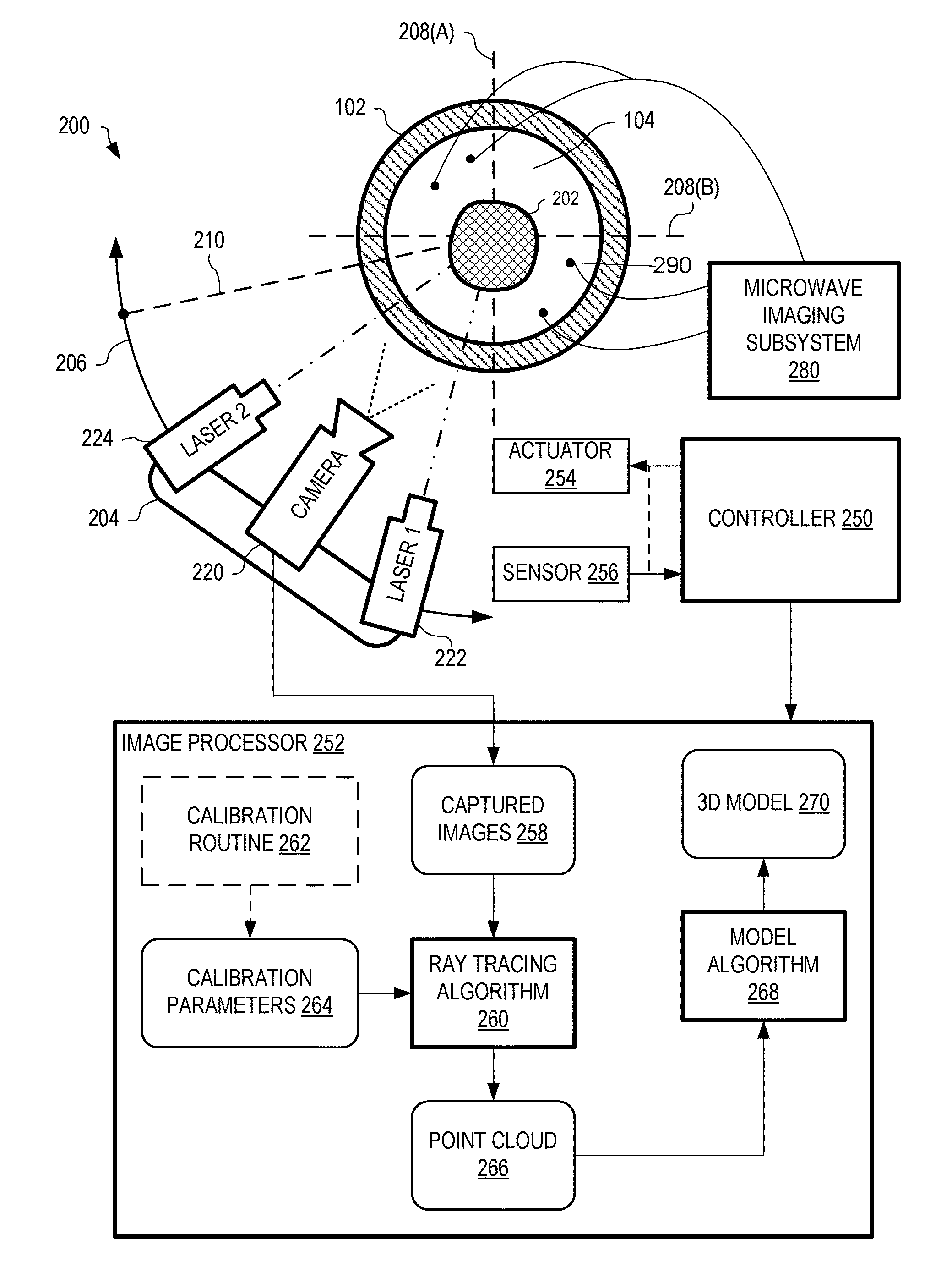
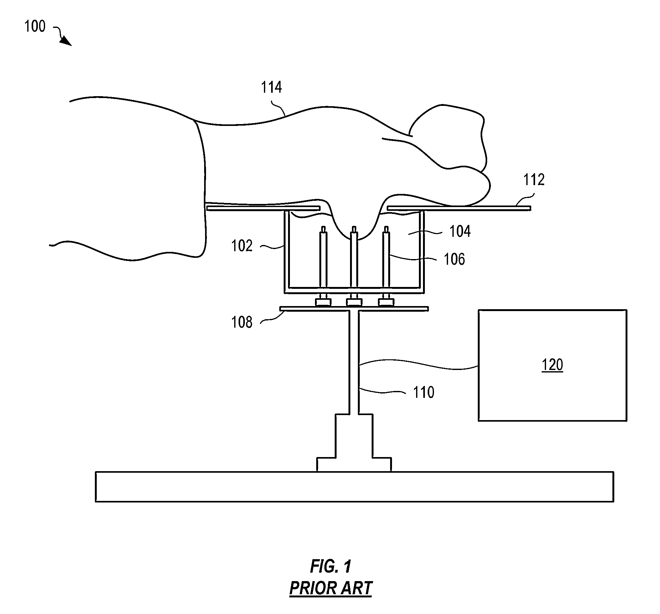
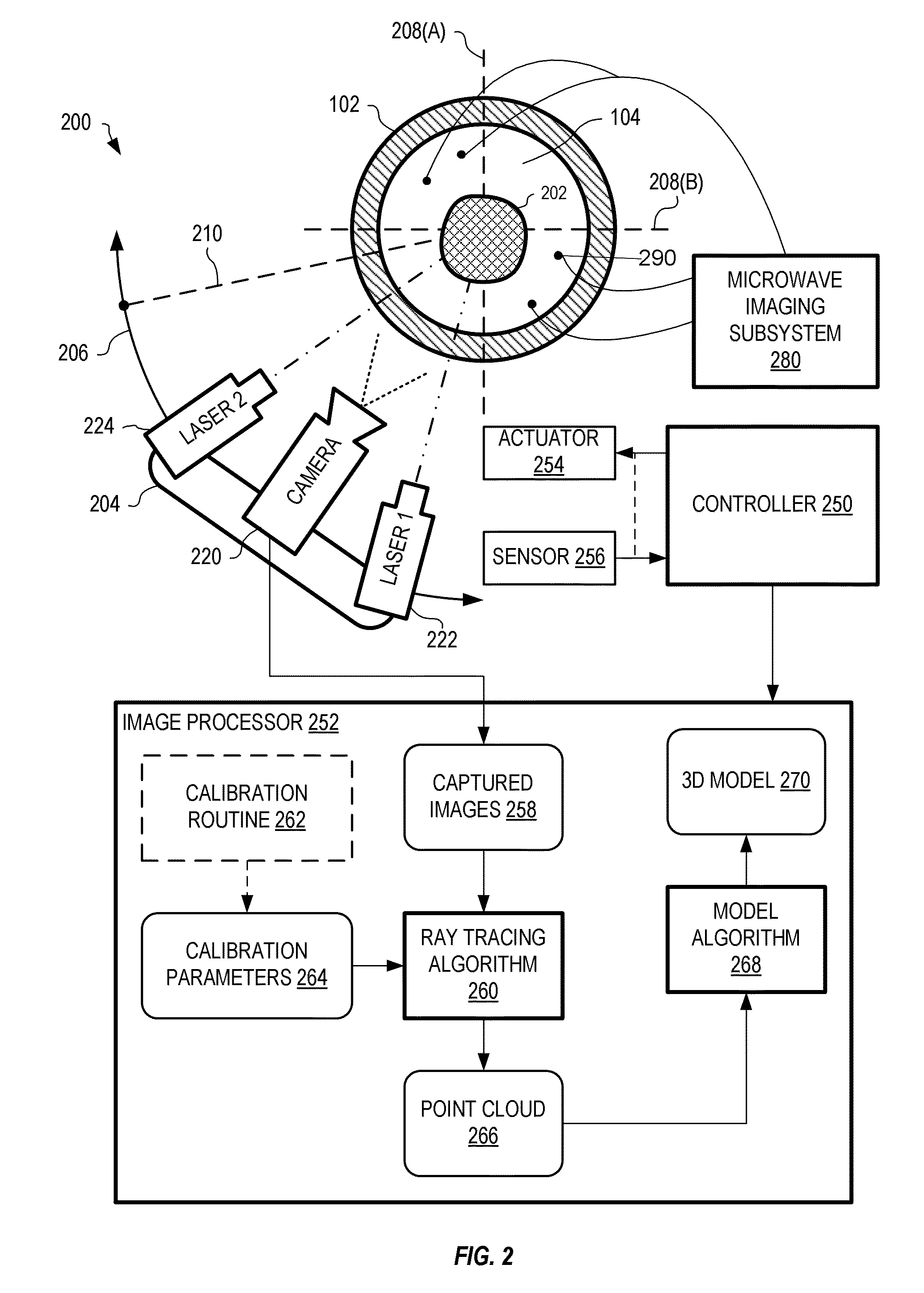
[0022]FIG. 1 is a schematic showing a prior exemplary microwave imaging system 100 for early detection of breast cancer that utilizes a transparent cylindrical tank 102 containing a transparent fluid 104 and an array of microwave antennae 106 positioned within tank 102 to pass low level microwaves through immersed breast tissue of a patient 114. Fluid 102 facilitates coupling of microwave-frequency RF signals from the antennas 102 to and through the breast tissue and back to antennas 102. System electronics 120 incorporates a microwave transmitter, a power divider, a switching network, microwave receivers, and a processor that cooperate to provide control over the operation of system 100 and the generation and reception of microwave signals through the array of antennas 106. Microwave imaging system 100 is described in detail within U.S. patent application Ser. No. 10 / 407,886, filed Apr. 4, 2003, and included within appendix A. Further details on the Microwave Imaging Spectroscopy G...


PUM


Abstract

Systems and methods generate a 3D model of a surface of an object immersed in a transparent liquid within a stationary cylindrical transparent tank. First and second laser line projectors and a camera are rotated around a central axis of the cylindrical tank. The first and second laser line projectors each generate a laser line perpendicular to a plane or rotation and aligned with the center of rotation. The camera images the object. An image from the camera is captured at each of several angular positions of the camera relative to a reference position of the stationary cylindrical tank. The captured images are processed to determine, for each laser line within each image, a plurality of 3D positions where the laser line is incident upon a surface of the object. In embodiments, images are corrected with ray tracing or image warping and registration functions.

Description

RELATED APPLICATIONS[0001]The application is a continuation of PCT Patent Application PCT / US2011 / 041448, filed Jun. 22, 2011 which claims priority to U.S. Provisional Patent Application 61 / 357,785, filed 23 Jun. 2010, the disclosures of which are incorporated herein by reference.U.S. GOVERNMENT RIGHTS[0002]The U.S. Government has certain rights in this invention as provided for by the terms provided by the National Institute of Health / National Cancer Institute for grant number PO1-CA080139.BACKGROUND[0003]Laser scanning of objects is typically performed through air. That is, the laser light passes through only one medium between a laser generator and the target object, and through the same medium between the object and an imaging camera. The object is typically rotated in the path of the laser line while the laser line generator and imaging camera remain stationary.[0004]Objects, including human or mammalian breasts or limbs, must often be immersed in a fluid when ultrasound, microw...

Claims


Application Information

Patent Timeline
Patent Type & Authority Applications(United States)
IPC IPC(8): H04N13/02H04N13/221
CPCA61B5/0091A61B5/0507A61B5/1077A61B5/4312G06T15/06G06T7/0057G06T2210/41H04N13/0221G06T1/0007G06T5/006G06T17/00G06T7/521H04N13/221G01B11/2518G01B2210/54G01B11/2509
Inventor PALLONE, MATTHEWMEANEY, PAUL M.PAULSEN, KEITH D.
Owner TRUSTEES OF DARTMOUTH COLLEGE THE
Why Eureka
Try Eureka