Axial Anti-friction bearing, in particular axial needle bearing

a technology of anti-friction bearings and needle bearings, which is applied in the direction of roller bearings, elastic bearings, mechanical equipment, etc., can solve the problems of reduced efficiency, increased wear of races, and reduced desired efficiency of automatic transmission, so as to achieve small race support and small width

Active Publication Date: 2013-05-30
SCHAEFFLER TECH AG & CO KG
View PDF4 Cites 8 Cited by
  • Summary
  • Abstract
  • Description
  • Claims
  • Application Information

AI Technical Summary

Benefits of technology

[0013]However, in certain applications it can also be advantageous to design the two bearing disks with different spring characteristics. In such cases, it is possible to use different sheet metal thicknesses for the two bearing disks with the same angle of incidence of the races, or to use equal sheet metal thicknesses for the bearing disks and to vary the angle of incidence of one race relative to the angle of incidence of the other race. Furthermore, another possibility for varying the spring characteristics of the bearing disks occurs when different sheet metal thicknesses are used for the bearing disks while the angles of incidence of the races also are different.
[0014]Moreover, according to claim 7, a useful enhancement of the axial roller bearing designed according to the invention, which likewise is independent of the particular embodiment, is that the races of the two bearing disks are additionally designed with circumferential annular beads directed towards the rolling elements, the beads having a smaller width than the width of the rolling elements. By means of such annular beads, it is possible to partially make the preloading of the bearing disks, which is relatively soft with a smooth disk spring shape, somewhat harder within the spring characteristic if this should prove to be advantageous for specific applications. In this design, furthermore, such annular beads are s

Problems solved by technology

However, under continuous operating conditions of such automatic transmissions, it has been shown that the axial needle bearings used still cause frictional losses that are a contributing cause of a reduction in the desired efficiency of the automatic transmission, and the reduction in said losses thus offers considerable potential, particularly against the background of present demands for reduction of CO2 emissions from motor vehicles with internal combustion engines.
The reduction in efficiency here can primarily be attributed to the frequent change of the axial needle bearings between the loaded and unloaded states resulting from the individual shifting operations in the automatic transmission.
Although the frictional torque resulting from the line contact of the rolling elements with their races is reduced in the unloaded state of the axial roller bearings, the aforementioned rolling element slip increases in this state to such a degree that a kinematically undesirable rolling of the rolling elements on the races takes place to the point where the rolling elements or the entire needle cage comes to a standstill, with the rolling elements merely

Method used


Image

  • Axial Anti-friction bearing, in particular axial needle bearing
  • Axial Anti-friction bearing, in particular axial needle bearing
  • Axial Anti-friction bearing, in particular axial needle bearing

Examples


first embodiment

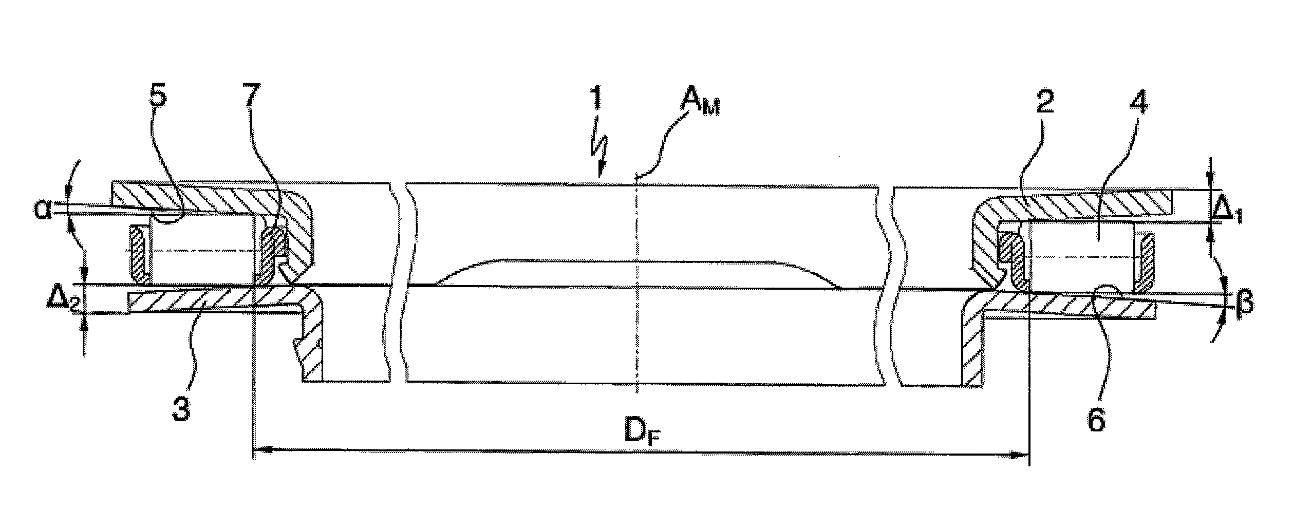
[0017]FIG. 1 an enlarged cross-section of an axial roller bearing designed in accordance with the invention;

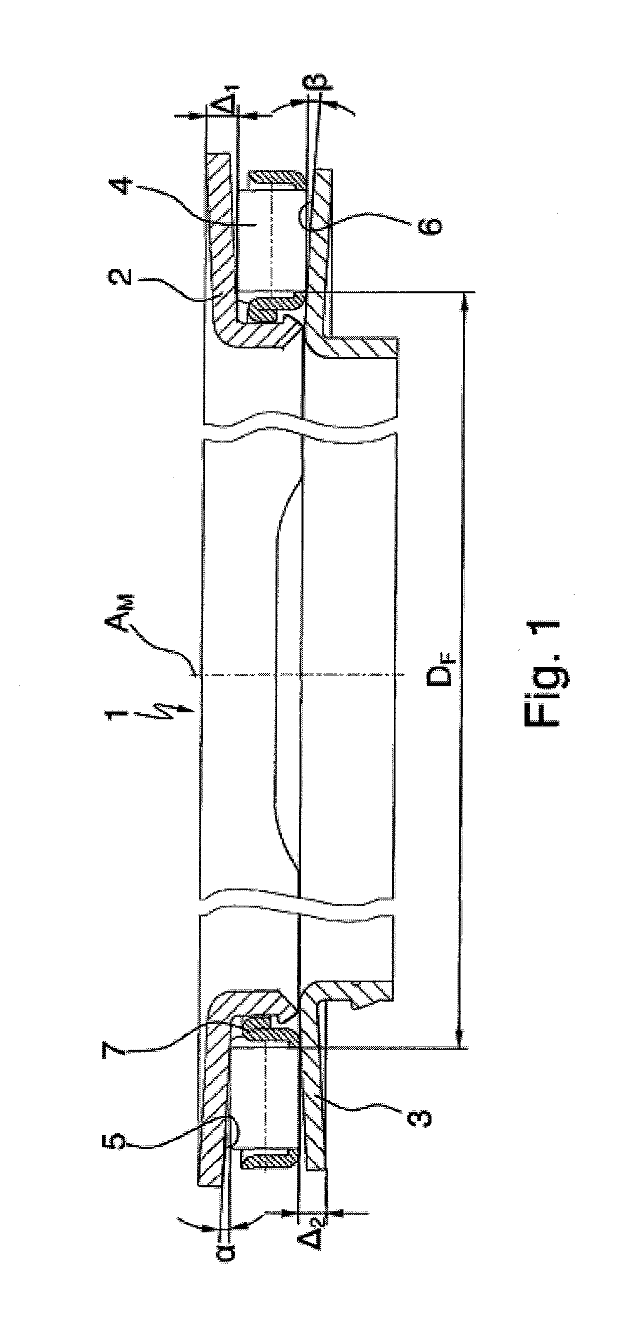
[0018]FIG. 2 an enlarged cross-section of a variant of the first embodiment of the axial roller bearing designed in accordance with the invention;

second embodiment

[0019]FIG. 3 an enlarged cross-section of an axial roller bearing designed in accordance with the invention.

DETAILED DESCRIPTION OF THE DRAWINGS

[0020]Visible in FIGS. 1 through 3 are three axial roller bearings 1, each implemented as a single-row axial needle bearing, which consist essentially of a first annular bearing disk 2 and a second annular bearing disk 3 that are each made of a thin-walled sheet steel, each of which has, formed on its inner diameter, a centering rib that is not labeled, and each of which is arranged at a distance from the other on a common center axis AM. In addition, the axial roller bearing 1 has a plurality of rolling elements 4 arranged next to one another that are implemented in the form of bearing needles that roll between the axial inner sides—implemented as races 5, 6—of the two bearing disks 2, 3, and that are held at uniform distances from one another by a bearing cage 7.

[0021]In addition, it is clearly evident from all three figures that the beari...


PUM


Abstract

The invention concerns an axial roller bearing (1), in particular an axial needle bearing, consisting essentially of a first annular bearing disk (2) and a second annular bearing disk (3) that are each made of a thin-walled sheet steel and are arranged at a distance from one another on a common center axis (AM), and of a plurality of rolling elements (4) arranged next to one another that roll between the axial inner sides—implemented as races (5, 6)—of the two bearing disks (2, 3) and that are held at uniform distances from one another by a bearing cage (7). According to the invention, the bearing disks (2, 3) of the axial roller bearing (1) are implemented as disk springs that deflect as a function of load and have races (5, 6) positioned at an angle, and are arranged relative to one another such that the rolling elements (4) have low-friction point contact in the unloaded state of the axial roller bearing (1) and only have load-bearing line contact with the races (5, 6) in the fully loaded state of the axial roller bearing (1).

Description

FIELD OF THE INVENTION[0001]The invention concerns an axial roller bearing according to the generic features of claim 1, and it can be implemented to particular advantage in axial needle bearings for supporting planet carriers or clutch carriers or for the impeller or turbine wheel in automotive automatic transmissions.BACKGROUND OF THE INVENTION[0002]The most common implementation of automotive automatic transmissions is what is known as torque converter transmissions, which differ from conventional and automated manual transmissions primarily through a shifting process that does not interrupt tractive force. Such automotive automatic transmissions generally use a hydraulic torque converter as the starting clutch, consisting of an impeller, a stator, and a turbine wheel, and are composed primarily of a varying number of multi-plate clutches and a combination of multiple planetary gear sets. All shifting and clutch operations in this design take place by means of various one-way clu...

Claims


Application Information

Patent Timeline
IPC IPC(8): F16C19/30F16C33/58
CPCF16C19/30F16C33/58F16C33/588F16C2240/34F16C2240/30F16C19/522F16C27/08F16C33/585Y02T10/86
Inventor FUGEL, WOLFGANGKRUHOFFER, WOLFRAM
Owner SCHAEFFLER TECH AG & CO KG
Why Eureka
Try Eureka