Wireless energy transfer system

a technology of energy transfer system and wires, which is applied in the direction of transformers/inductance circuits, basic electric elements, inductances, etc., can solve the problems of power consumption at the receiver, methods that are sensitive to the orientation of the device, and prior art solutions such as rfid may prove difficult, so as to avoid unnecessary radiation to humans

Inactive Publication Date: 2013-05-30
SONY CORP
View PDF5 Cites 291 Cited by
  • Summary
  • Abstract
  • Description
  • Claims
  • Application Information

AI Technical Summary

Benefits of technology

[0011]2. Wirelessly charging mobile electronic devices which consume less than a dozen millwatts, yet avoiding unnecessary rad

Problems solved by technology

However such methods maybe sensitive to the device orientation.
One technical challenge may be how to locate a receiver accurately at very low power consumption at the receiver.
Prior art solutions such as RFID may prove difficult because:
A generic RFID module at UHF band, if mounted in the transmitter and receiver, may not allow for beam scanni

Method used


Image

  • Wireless energy transfer system
  • Wireless energy transfer system
  • Wireless energy transfer system

Examples


Embodiment Construction

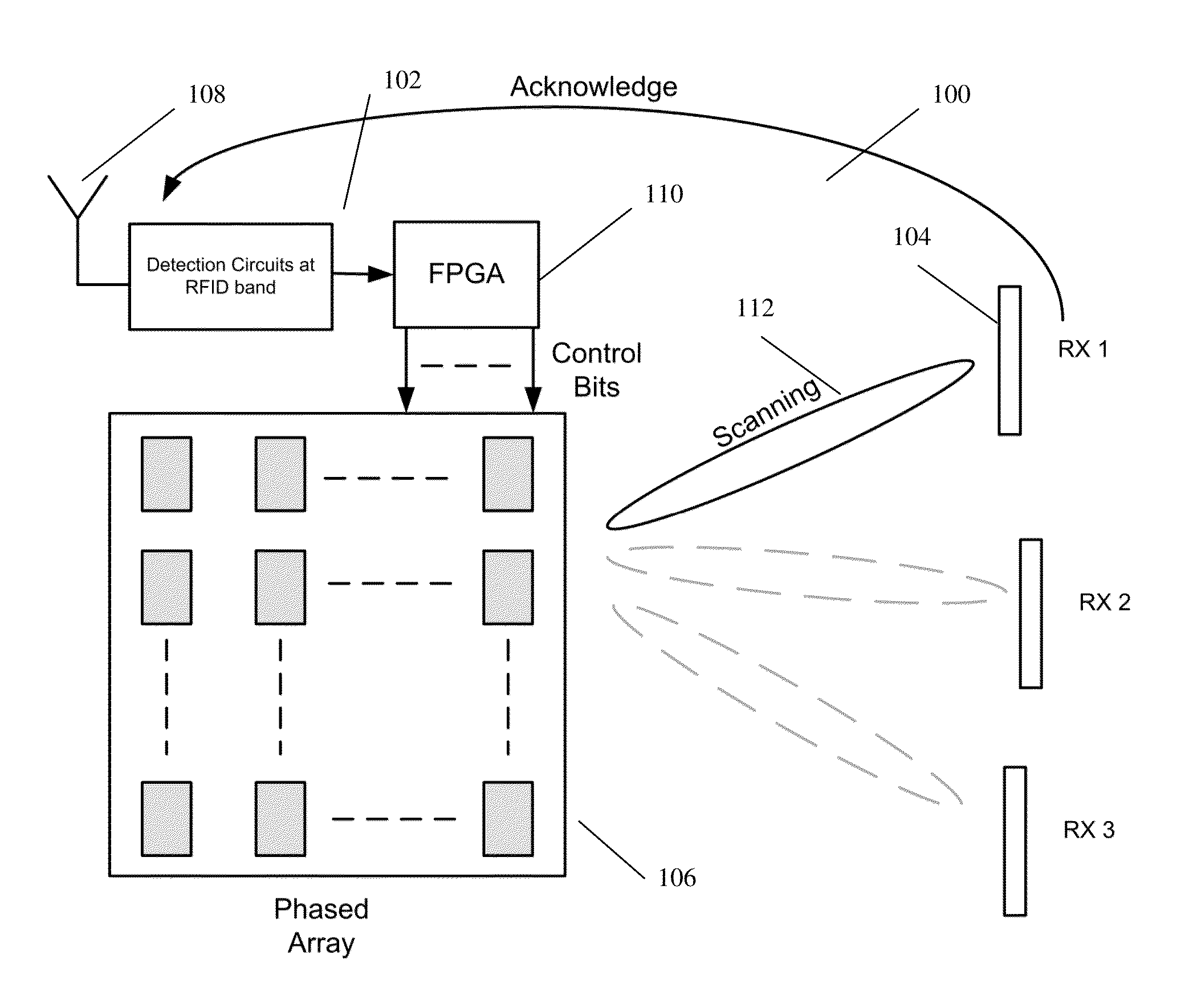
[0037]The system 100 is shown in FIG. 1 for wireless energy transfer between a base station 102 and a mobile electronic device 104. The base station 102 includes a 2.4 GHz steerable antenna 106 for transmitting and a 860 MHz antenna 108 for receiving acknowledgements. A Field Programmable Gate Array (FPGA) 110 acts as a controller. The FPGA 110 controls the steerable antenna 106 to send focused burst of RF radiation scanning across a range of sectors 112 searching for any devices 104. Based on any acknowledgements received, the FPGA 110 will make a determination on the location of any identified devices 104. The steerable antenna 106 then focuses continuous RF radiation towards the location to transfer energy to the device 104. The location is tracked and if the deice 104 moves to another sector, the location is updated.

[0038]The steerable antenna 106 is a phased array with M×N elements. It transmits RF energy at 2.45 GHz and has a range of a couple of meters. The coverage area is d...


PUM


Abstract

A wireless energy transfer system comprising: a transmitter configured to beam scan RF radiation across a plurality of sectors at a first frequency, a receiver storing energy from the RF radiation, and sending acknowledgements at a second frequency, the first frequency being significantly different from the second frequency, and a controller configured to direct wireless energy transfer from the transmitter substantially at the receiver based on the acknowledgements.

Description

FIELD[0001]The present invention relates to a wireless energy transfer system.BACKGROUND[0002]With mobile electronic devices becoming more popular, ease and flexibility of charging the mobile device's battery is of increasing importance. Typically most prior art devices use a mains connected converter which is hard wire connected to the mobile device to provide a low voltage DC supply for charging.[0003]An alternative to wired charging is wireless charging. Prior art examples of wireless energy transfer include induction, resonant coupling, electromagnetic radiation and laser. Induction may only be useful where the device is very close, such as wireless dock charging for electric toothbrushes, or a transformer. At mid distances resonant coupling is used, such as in some RFID and smart cards. Because the efficiency reduces dramatically with distance, for larger distances a high degree of directionality is required. Longer distance options include EM radiation and laser. However such ...

Claims


Application Information

Patent Timeline
IPC IPC(8): H02J17/00
CPCH02J17/00H02J50/23H02J50/27H02J50/402H02J50/90
Inventor XIA, JING JINGNG, WEI BENGMASUDA, HISASHI
Owner SONY CORP
Why Eureka
Try Eureka