Eureka AIR delivers breakthrough ideas for toughest innovation challenges, trusted by R&D personnel around the world.

Airless pump system

Inactive Publication Date: 2013-06-06
YONWOO CO LTD
View PDF15 Cites 20 Cited by
  • Summary
  • Abstract
  • Description
  • Claims
  • Application Information

AI Technical Summary

Benefits of technology

The present invention is an airless pump dispenser for a fluid that includes a housing with a top and bottom, an airless pump mounted in the housing, a movable piston with a top and bottom, and a dispenser at the top of the housing for dispensing the fluid. A spring member is affixed to the bottom of the housing or the movable piston. The movable piston includes sealing means for airtight sealing with the inner surface of the housing. The dispenser includes a one-way valve controlling the flow of the fluid, a pump housing, a pump piston, and a spring member. The pump piston includes at least one opening and a sealing flap covering the opening. The airless pump dispenser allows for a vacuum to draw the fluid from the dispensing space through the one-way valve when the pump piston is in the dispensing position. The dispenser also includes a return spring for returning the pump piston from the dispensing position to the initial rest position. The movable piston includes an inner conduit for the fluid connected to the pump piston in the movable exit housing. The pump piston can be made of a helically coiled spring or an accordion bellows. The invention provides an improved airless pump dispenser that allows for airtight sealing with the housing, creates a vacuum to draw the fluid from the dispensing space, and includes a spring member for efficient operation.

Problems solved by technology

A problem encountered with conventional airless pump devices is that in order to operate properly the package must be filled with little or no headspace.
Thus, particularly in connection with water-based products being utilized in these dispensers, a problem is created if the product freezes, such as during shipment or delivery.
This causes the product to expand, pushing the pump out of the container or causing the container to crack or rupture.

Method used


Image

  • Airless pump system
  • Airless pump system
  • Airless pump system

Examples


Embodiment Construction

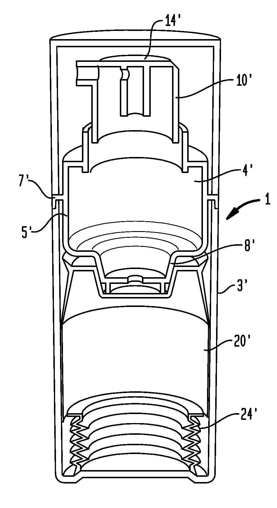
[0031]The airless pump dispensers to which the present application is directed are dispensers for various liquid or semi-liquid compositions (generally referred to as “fluids,” and thus including a large variety of flowable compositions), which are dispensed by drawing a vacuum with an airless pump upon depressing an activator of some type, generally disposed at the top of the dispenser, thus permitting the fluid to exit from a nozzle thereon. Thus, these airless pump dispensers act by the activation of a pump to eject product from a container in a specific dose by creating a vacuum within the container. As the pump evacuates product by creating a vacuum, a piston at the bottom of the container moves upwardly to equalize the force created by the vacuum so as to return the device to ambient atmospheric pressure before the next such activation.

[0032]Such airless pumps are currently primarily used in order to totally evacuate a product from the container. In a preferred embodiment, spe...


PUM


Abstract

Airless pump dispensers for various fluids are disclosed including an airless pump mounted in a housing, a movable piston mounted for moving within the housing starting at the bottom thereof, a dispenser at the top of the housing for receiving fluid from the airless pump and dispensing it, and a spring disposed at the bottom of the housing in contact with the bottom of the movable piston and having an insufficient driving force to independently move the movable piston within the housing when the housing contains the fluid.

Description

FIELD OF THE INVENTION[0001]The present invention generally relates to airless pump dispensers. More particularly, the present invention relates to airless pump dispensers which are configured to deal with various external conditions.BACKGROUND OF THE INVENTION[0002]Airless pump dispensers have become extremely popular for a variety of reasons. Since they operate under a vacuum, they are particularly useful in connection with certain personal care products and pharmaceutical products, particularly those which can be degraded upon contact with air. These airless pump dispensers have also become more of a standard for use in the total evacuation of viscous products from their containers. In the past these viscous products have been packaged in jars or flexible tubes. The airless pump dispensers are thus preferred over these products due to the elimination of contamination of the product by the need to put your hand in the jar, and in order to maintain dispensing, and to provide virtua...

Claims


Application Information

Patent Timeline
IPC IPC(8): G01F11/00
CPCA45D34/04B05B11/0048B05B11/0008A45D34/041B05B11/3001B05B11/028B05B11/1023B05B11/1047B05B11/1069B05B11/1074B05B11/1001
Inventor CSASZAR, EDWARD F.
Owner YONWOO CO LTD
Why Eureka
Eureka Blog
Learn More