EUV Exposure Apparatus

a technology of exposure apparatus and euv light, which is applied in the field of reflection optical elements, can solve the problems of reducing the image quality of the substrate or wafer w, unable to meet the needs of optical lenses, and unable to work with reflective optical elements like mirrors or like diffractive optical elements, so as to reduce the influence

Active Publication Date: 2013-06-06
CARL ZEISS SMT GMBH +1
View PDF6 Cites 38 Cited by
  • Summary
  • Abstract
  • Description
  • Claims
  • Application Information

AI Technical Summary

Benefits of technology

[0014]The present invention is directed to an improved EUV-projection lens to further reduce the influence of any temperature variation to deformations and / or position variations of the reflective optical elements or mirrors inside such a projection lens.

Problems solved by technology

Since in the very deep ultraviolet wavelength range almost all optical materials become opaque, there are no suitable materials for optical lenses for wavelength below about 157 nm.
Using even shorter wavelengths for the projection light, the projection lenses can only work with reflective optical elements like mirrors or like diffractive optical elements.
Each deviation from the desired specification results in a degradation of the image quality on the substrate or wafer W. Usually the specification is such that a deviation from the surface figure (the required or specified dimensions of the shape of the surface) of less than one tenth of the used projection wavelength is required.
To achieve the above mentioned mechanical precisions, one further problem is the absorption of the projection beam 4 by the mirrors 21, 22, 23, 24.
The reduced pressure or vacuum conditions significantly reduce the technical solutions for the above mentioned problems regarding the deformation of mirrors and their active or passive position control.
Especially temperature control systems for controlling a temperature of components inside the EUV lithographic projection exposure system are quite often limited to certain technical solutions which are not essentially based on thermal convection principles.

Method used


Image

  • EUV Exposure Apparatus
  • EUV Exposure Apparatus
  • EUV Exposure Apparatus

Examples


second embodiment

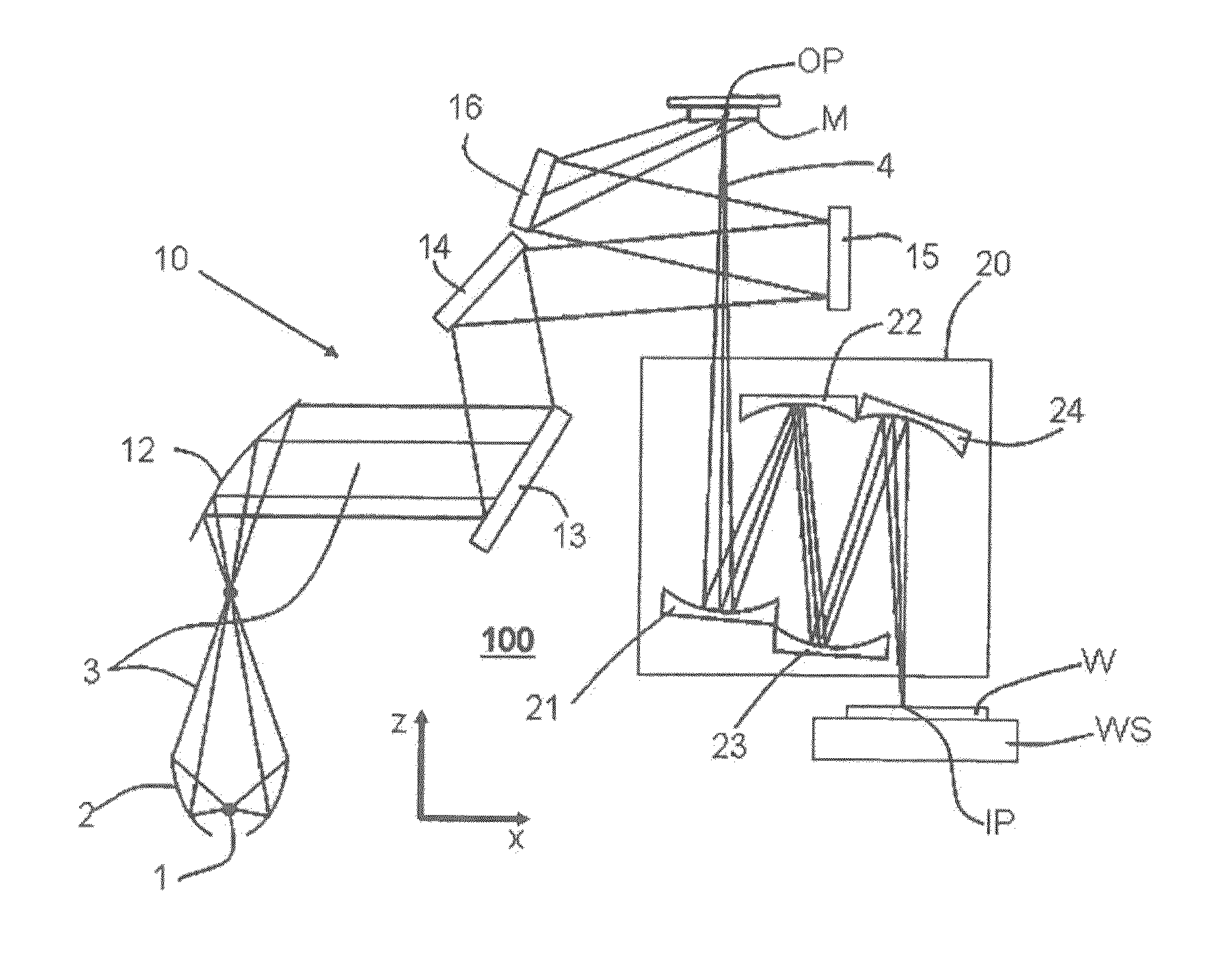
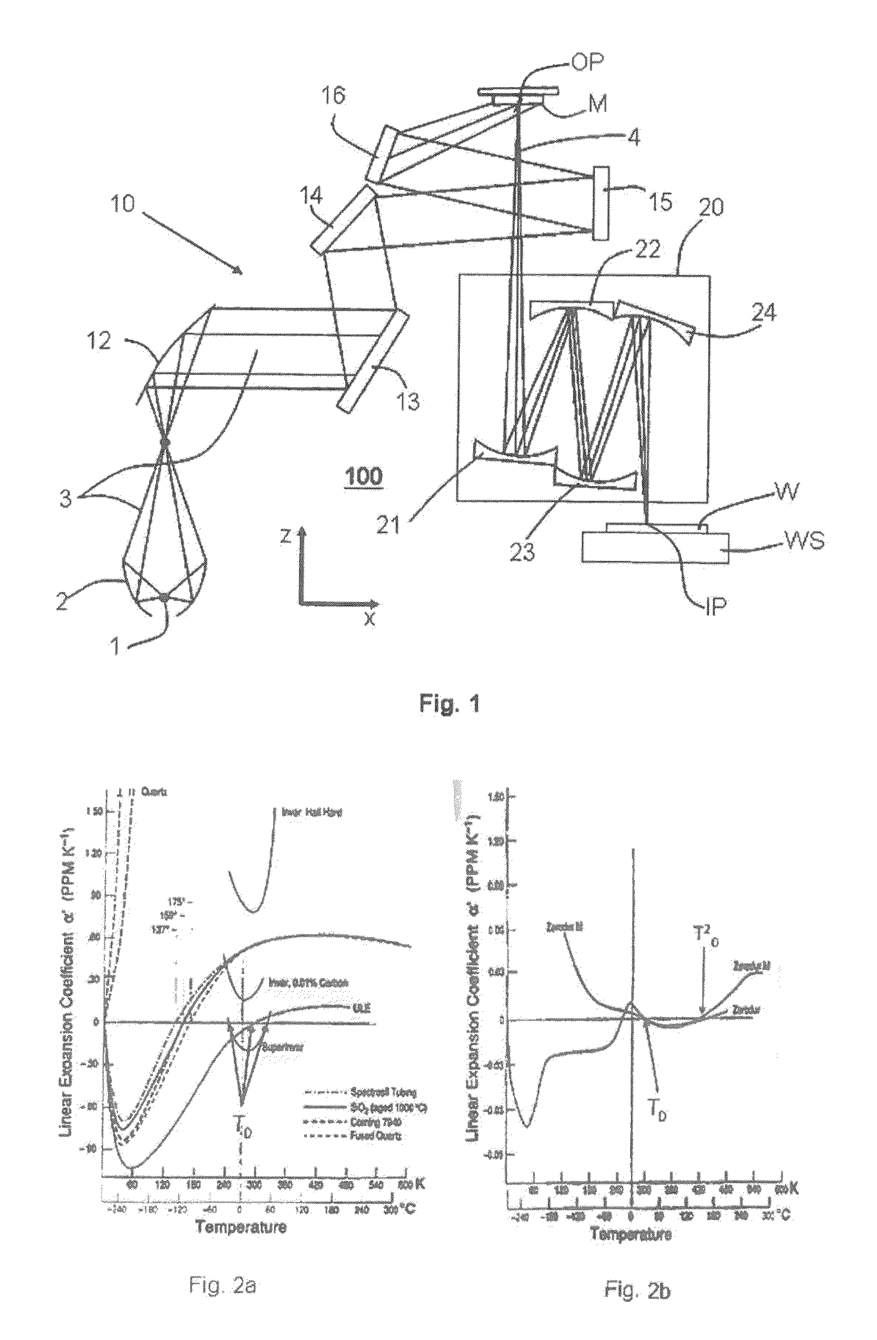
[0086]As a further second embodiment of such a first projection lens the lens can comprise four or six reflective optical elements Mi or mirrors (as e.g. shown in FIG. 1 and in FIG. 6) and preferably the projection lens is designed to be exposed with an exposure power of more than 10 W. In this case the absolute value of the difference between the zero cross temperatures T0m, T0n is more than 8K, expresses as abs(T0m−T0n)>8K. For the 6-mirror lens of FIG. 6, FIG. 9 clearly shows this for the mirrors M5 and M4 or M6. The zero cross temperatures of these mirrors differ by more than 8 K if the exposure power goes above 10 W.

third embodiment

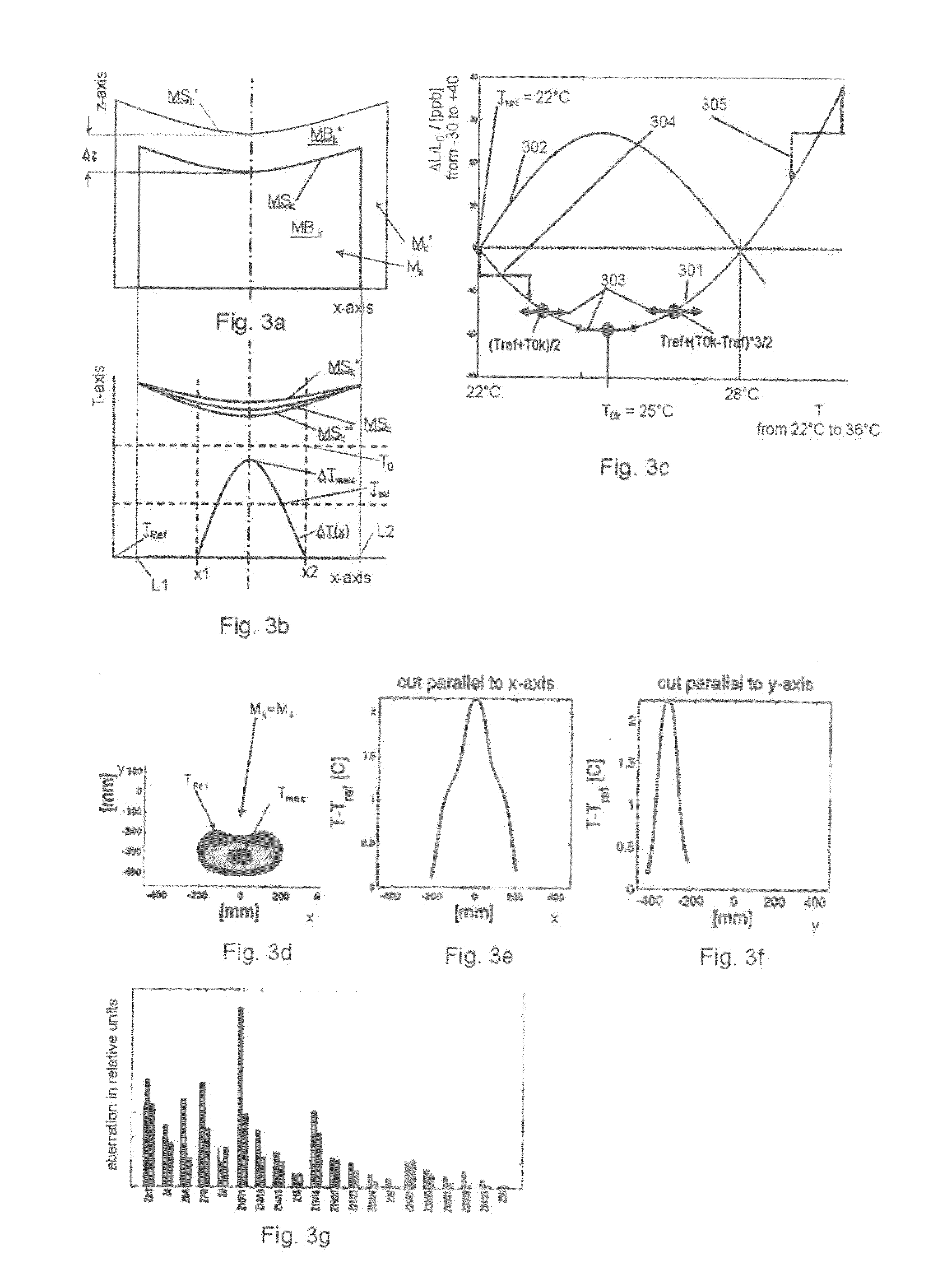
[0087]The first projection lens and its previous embodiments in a third embodiment may comprise a support structure for passively or actively supporting the reflective optical elements Mi, as it was described in connection with FIG. 4 and FIG. 5. The temperature of at least a part of the support structure is at a reference temperature TRef, which is e.g. selected as 22° C. Further, the lens in accordance with an embodiment of the first lens comprises a heater 300 for heating at least one of the mirror bodies MBn, MBm which comprise the materials with the different zero cross temperatures. A temperature control system 200 controls the temperature of the at least one heated mirror body MBn, MBm to a temperature Tk. Preferably the heater 300 is made such that the body can be homogenously heated. This means that the body MBn, MBm is homogenously heated in at least one dimension of the body. Various types of heaters 300 will be described below in this description.

fourth embodiment

[0088]In an further fourth embodiment of the first lens (and its previous embodiments), there, without the operation of the just mentioned heater 300, the exposure of the reflective surfaces MSm and MSn of the bodies MBn, MBm with EUV light, results in temperature distributions ΔTn(x,y,z)=(Tn(x,y,z)−TRef), ΔTm(x,y,z)=(Tm(x,y,z)−TRef) of the bodies MBn, MBm relative to the reference temperature TRef with respective average and maximum temperatures ΔTnav, ΔTmav and ΔTnmax and ΔTmmax. The EUV light with which the reflective surfaces MSm and MSn are exposed is reflected by the illuminated reticle and comprises a spatial distribution of angular, polarization and intensity parameters in accordance with an illumination setting. In this embodiment at least one zero cross temperatures T0m, T0n is selected higher than the maximum of the highest reference temperature TRef and the respective average or maximum temperature ΔTmav+Tref or ΔTmmax+Tref, ΔTnav+Tref or ΔTnmax+Tref, based on the respec...


PUM


Abstract

A projection lens of an EUV-lithographic projection exposure system with at least two reflective optical elements each comprising a body and a reflective surface for projecting an object field on a reticle onto an image field on a substrate if the projection lens is exposed with an exposure power of EUV light, wherein the bodies of at least two reflective optical elements comprise a material with a temperature dependent coefficient of thermal expansion which is zero at respective zero cross temperatures, and wherein the absolute value of the difference between the zero cross temperatures is more than 6K.

Description

CROSS REFERENCE TO RELATED APPLICATIONS[0001]This application is a continuation application of international patent applications PCT / EP2011 / 062996, PCT / EP2011 / 063002, PCT / EP2011 / 062997 and PCT / EP2011 / 062995, all filed Jul. 28, 2011, designating the United States and claiming priority from U.S. provisional application Ser. No. 61 / 369,142, filed Jul. 30, 2010, and the entire content of the above applications is incorporated herein by reference.FIELD OF THE INVENTION[0002]The present invention relates to a reflective optical element for reflecting light in a wavelength range less than 50 nm in an EUV-lithographic projection exposure system. Further, it relates to an EUV projection lens of an EUV-lithographic projection exposure system and to a method to configure an EUV projection lens.BACKGROUND OF THE INVENTION[0003]To reduce the size of micro-structured devices like semiconductor circuits (e.g. integrated, analogue, digital or memory circuits, thin-film magnetic heads) with the tech...

Claims


Application Information

Patent Timeline
Patent Type & Authority Applications(United States)
IPC IPC(8): G03B27/54G02B5/08G02B3/00
CPCB82Y10/00G03B27/542G02B7/1815G02B17/0647G02B27/0043G03F7/70233G03F7/70825G03F7/70891G03F7/70958G21K1/062G21K2201/061G21K2201/064G02B3/00G02B5/08G02B5/0891G02B27/18G03F7/70316G02B5/0816G03F7/7015G03F7/702G02B5/00
Inventor BAER, NORMANLOERING, ULRICHNATT, OLIVERWITTICH, GEROLAUFER, TIMOKUERZ, PETERLIMBACH, GUIDOHEMBACHER, STEFANWALTER, HOLGERKWAN, YIM-BUN-PATRICKHAUF, MARKUSSTICKEL, FRANZ-JOSEFVAN SCHOOT, JAN
Owner CARL ZEISS SMT GMBH
Why Eureka
Try Eureka