
Fibre composite profile component and process and apparatus for continuous production

a fiber composite and composite material technology, applied in the field of fiber composite profile components, can solve the problems increased production costs, and increased production costs, and achieves the effects of short cycle time, high production efficiency, and cost-effectiveness

Inactive Publication Date: 2013-06-06
ZF FRIEDRICHSHAFEN AG
View PDF25 Cites 19 Cited by
  • Summary
  • Abstract
  • Description
  • Claims
  • Application Information

AI Technical Summary

Benefits of technology

The present invention aims to provide a new method for producing fiber composite profile components that overcomes the limitations of existing methods. This method allows for the continuous production of high-quality profile components that are cost-effective, reproducible, and have uniform quality. Additionally, this method allows for the production of profile components with complex cross-sectional shapes and the ability to reinforce or thicken specific areas during the primary forming process. This eliminates the need for re-work or subsequent mounting on the produced profile, reducing labor and materials costs.

Problems solved by technology

In particular, simple standard profiles with a straight, unchanging cross section over the profile length have been produced for a long time, usually using traditional pultrusion processes.
However, pultrusion processes are principally limited to the manufacture of unidimensional, linear or straight profiles.
However, these profiles, in turn, are subject to additional limitations in terms of the producible profile cross sections.
In any case, however, the known pultrusion processes are limited to producing profiles with a smooth, even profile surface and at the same time, with an unvarying profile cross section along the entire length of the profiles.
Likewise, pultrusion processes do not allow profile characteristics that vary over the length of the profile such as are generally needed to introduce force in the form of reinforced force introduction points or inserts for force application in the case of complex applications.
This means that reinforcements or inserts of this kind can, at best, be added to a finished pultrusion profile later, for which time-consuming reworking is required and which may be accompanied by a possible weakening of the fiber structure or of the fiber cohesion.
Last but not least, the quality of the finished carbon fiber composite profile that can be achieved using the known pultrusion processes is limited, among other things due to the lack of a defined pressing process when the impregnated fiber bundle passes through the molding die.
In particular, the production of profile components with a high reinforcement / matrix volume ratio with concomitant minimal air entrapment and high dimensional stability, which is generally required for demanding applications, is difficult or nearly impossible to achieve using the known pultrusion methods.
Due to the described limitations of the known pultrusion methods, components that are demanding both in terms of their shape and material properties are therefore still subject to time-consuming, individual production using conventional lamination methods, possibly from prepregs, or by means of resin transfer molding or pot molding.
Since the latter methods are usually limited to comparatively small components that are not very mechanically resilient, the complex layered production of profiles and components from prepregs with subsequent pressing and curing until the finished component is obtained has, until now, been the only option for especially demanding functional or profile components.
The cycle times for producing one component are accordingly long and the associated production costs are accordingly high.
This process and the associated apparatus known from prior art are limited, however, to the production of straight, prismatic profiles.

Method used


Image

  • Fibre composite profile component and process and apparatus for continuous production
  • Fibre composite profile component and process and apparatus for continuous production
  • Fibre composite profile component and process and apparatus for continuous production

Examples


Embodiment Construction

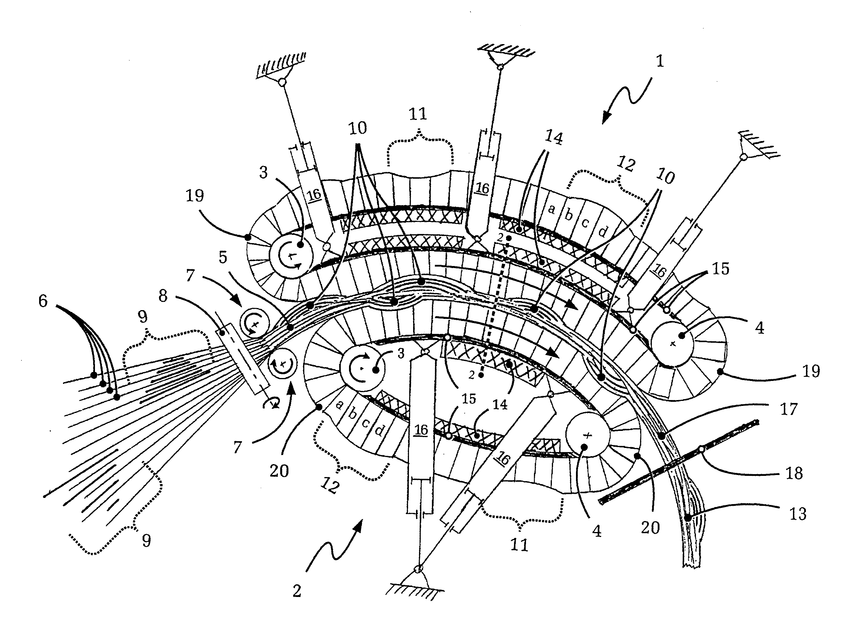
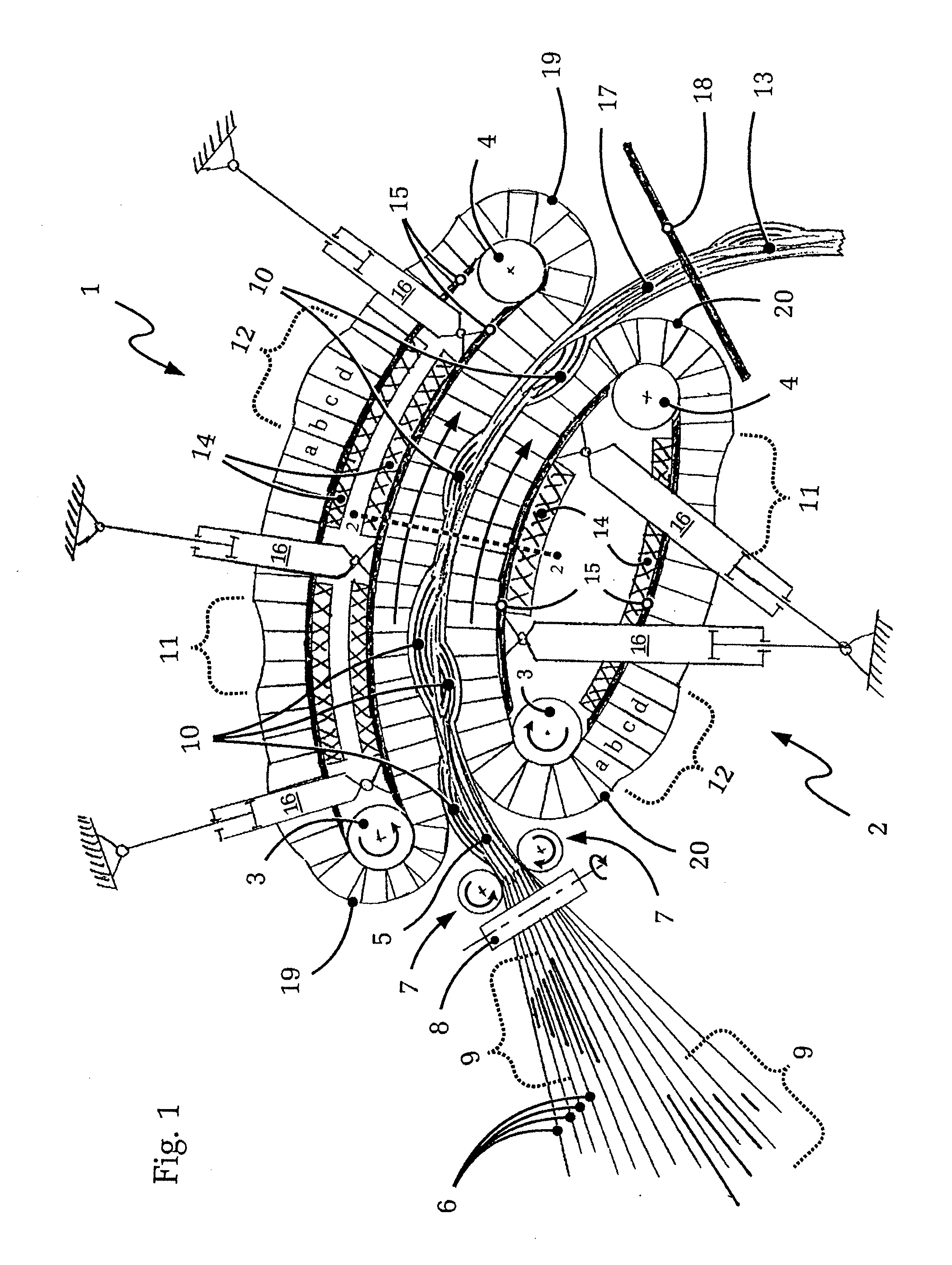
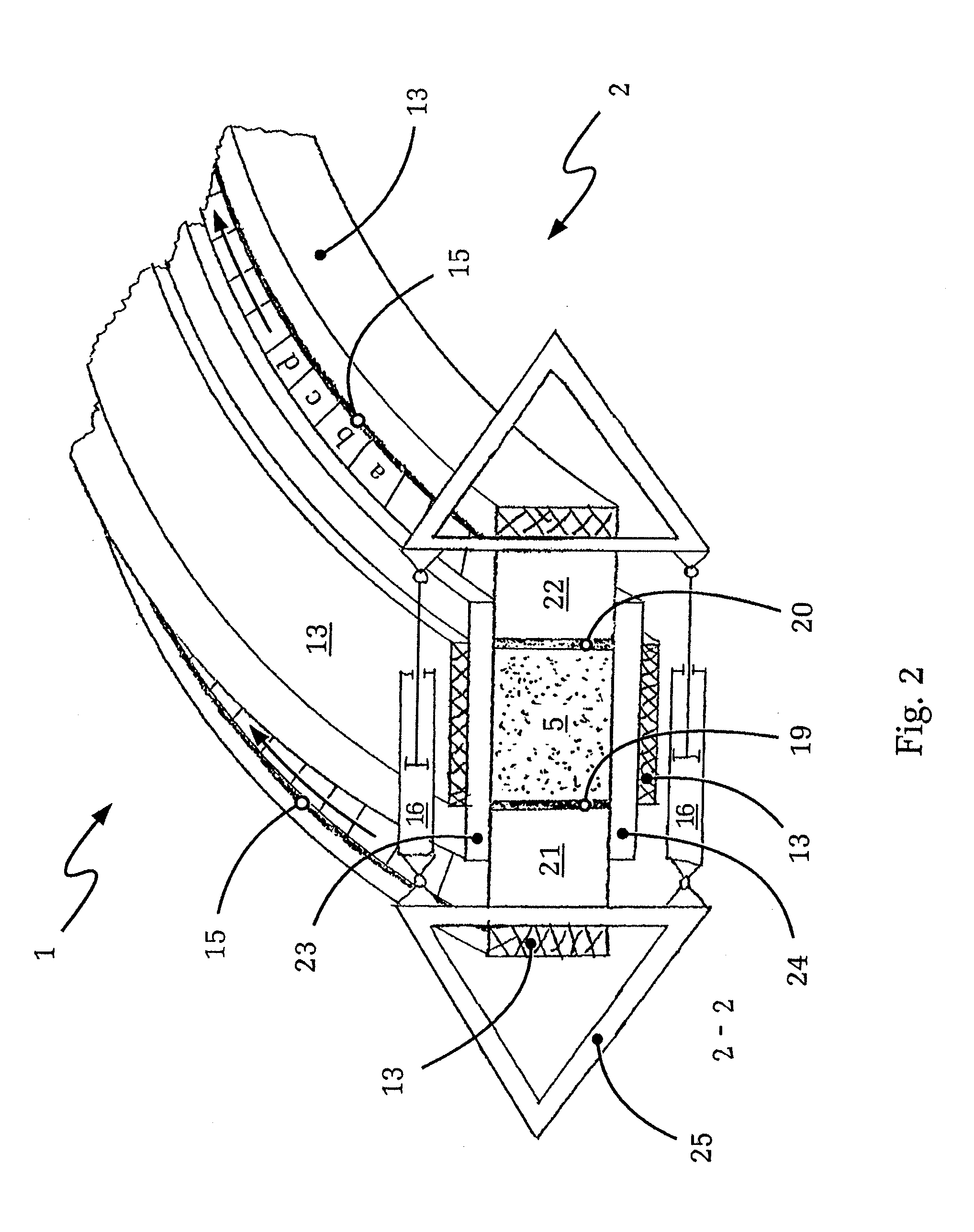
[0081]FIGS. 1 and 2 show different views of a forming chain system according to the invention for producing the fiber composite molded part, likewise according to the invention, based on the inventive method also according to the invention.

[0082]In FIG. 1, first of all, two forming chains 1, 2 disposed in the forming chain system in a rotary manner are shown. In the embodiment shown, the forming chains 1, 2 are each guided over a pair of deflecting rollers 3, 4 and if necessary driven in the direction of movement through the forming chain system by the preform batch 5 by means of the deflection rollers 3, 4. The driving can, in particular, be CNC controlled in order to ensure the feed rate, as well as additional associated process variables, in particular such as matrix content, component cross section and duration of cuing, are maintained as precisely as possible.

[0083]In the embodiment shown, the preform batch 5 is formed by a number of fed continuous fiber strands 6, continuous w...


PUM

PropertyMeasurementUnit
weight ratioaaaaaaaaaa
lengthaaaaaaaaaa
radius of curvatureaaaaaaaaaa

Abstract

A process for continuous production of profile components of fiber composite material by a forming chain system, an associated profile component and the chain system for its continuous production. The method draws on the forming chain system having at least one forming chain. Here, preform batch of fiber strands, impregnated with matrix material and / or woven fiber webs, knit webs or nonwoven webs, are brought to the system at the working run of the at least one forming chain and are guided through the forming chain system, forming a continuous profile containing the profile component with a variable cross section over the profile length and / or with a profile longitudinal axis with virtually any desired extent. The profile components can be provided with local reinforcements, add-on parts of inserts, for example, for introducing force, as early as during primary forming.

Description

[0001]This application is a National Stage completion of PCT / EP2011 / 053672 filed Mar. 11, 2011, which claims priority from German patent application serial no. 10 2010 002 988.2 filed Mar. 17, 2010.FIELD OF THE INVENTION[0002]The invention relates to a profile component of fiber composite materials and a process and an apparatus for its continuous production.BACKGROUND OF THE INVENTION[0003]Profile components of fiber composite materials and process and apparatuses for their continuous production are, in principle, known from prior art. Such profile components are used in a wide variety of areas of engineering. This includes reinforcement profiles of all kinds used to build aircraft fuselages or boat hulls according to the principles of light-weight construction, for example standard design profiles such as pipes, profiled beams, and solid or flat profiles, in addition to functional profile components such as wheel control or leaf spring elements.[0004]In particular, simple standard...

Claims


Application Information

Patent Timeline
Patent Type & Authority Applications(United States)
IPC IPC(8): B29C47/00F16F1/368B29C48/08B29C48/09
CPCB29C47/0023Y10T428/24479B29C47/0021B29L2031/008B29C70/504F16F1/368B29C47/0066B29D99/0007B29C48/08B29C48/09B29C48/0022
Inventor HOFMANN, PETER
Owner ZF FRIEDRICHSHAFEN AG
Learn More