Vision-guided alignment system and method

a technology of vision-guided alignment and alignment system, which is applied in the field of vision-guided alignment system, can solve the problems of complex, time-consuming, expensive, and time-consuming high-speed image processing utilized by visual servoing, and achieves the effects of simple structure, high deployment and maintenance cost, and high cos

Active Publication Date: 2013-06-13
ABB (SCHWEIZ) AG
View PDF2 Cites 56 Cited by
  • Summary
  • Abstract
  • Description
  • Claims
  • Application Information

AI Technical Summary

Benefits of technology

[0010]It is another aspect of the present invention to provide a vision-guided alignment system to align a plurality of components comprising a robotic gripper configured to have one component relative to another component, and a camera coupled to a processor, said camera generating an image of the components, wherein a simulated robotic work cell generated by said processor calculates initial calibr

Problems solved by technology

Whereas, the difficulty in automating electronic device assembly is due to the unique characteristics of the small-scale or small-sized electronic components involved, which are typically in the range of 1 to 10 mm, and which must be assembled together with tight spatial tolerances.
Model calibration techniques rely on obtaining an accurate camera model calibration and generating an accurate robot kinematic model to achieve precise component positioning during automated robotic alignment and assembly, which is expensive, complex, and time-consuming.
Unfortunately, the high-speed image processing utilized by visual servoing is complex and costly to deploy and maintain.
However, because assembly features of the component are not visually accessible by the imaging camera, it is difficult to accurately measure the distances between visual features and assembly features manually.
Unfortunately, the error resulting from the manual measurement results in an inaccurate robot camera model that is generated based on the position of the visual features.
Thus, if the robot camera model is inaccurate, the robot is unable to align or assemble the components accurately with high precision, which is unwanted.
Moreover, identifying the insertion positions tha

Method used


Image

  • Vision-guided alignment system and method
  • Vision-guided alignment system and method
  • Vision-guided alignment system and method

Examples


Embodiment Construction

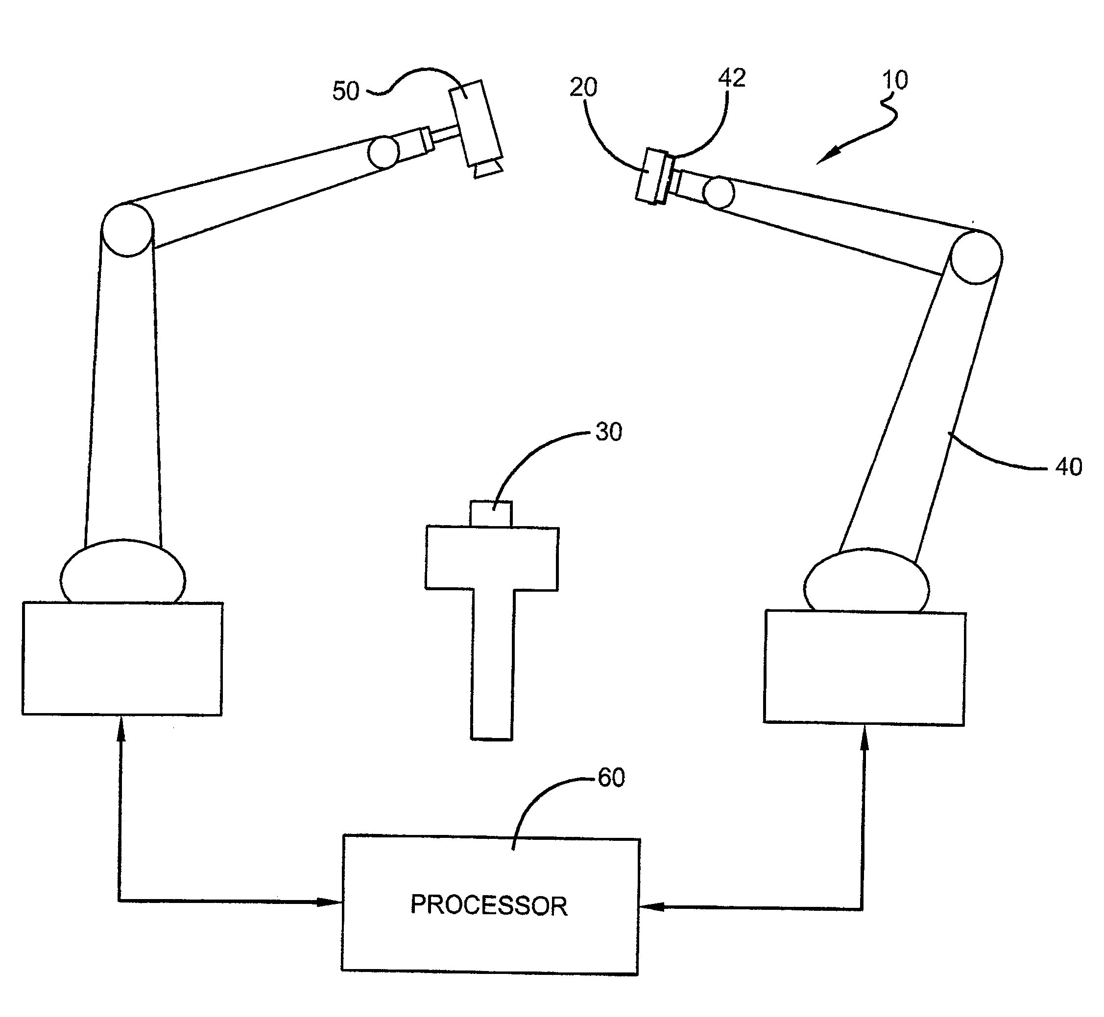
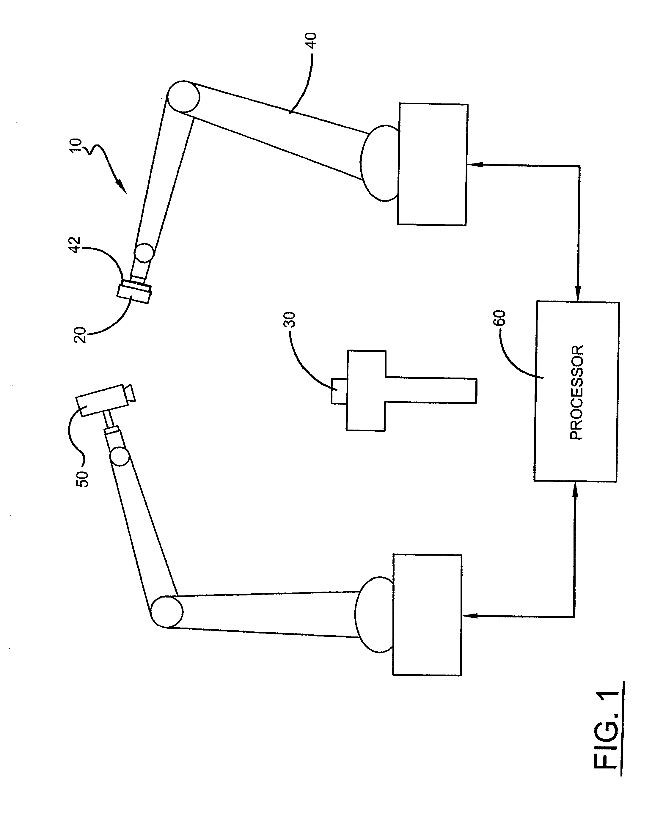
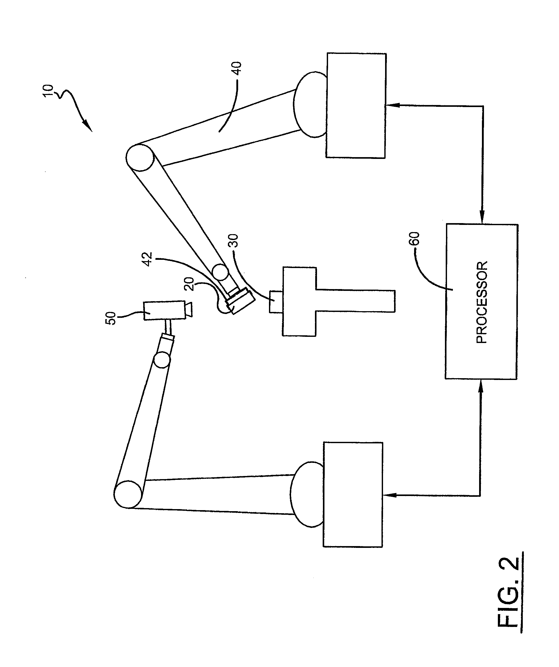
[0018]A system and method for automatically initializing a camera space manipulation (CSM) control process algorithm for a vision-guided alignment system 10 used to achieve precision alignment and / or tight-tolerance assembly of structures, such as small-scale components for electronic devices, is shown in the Figs. Specifically, with reference to FIG. 1, to align and / or couple a structural feature of a grasped electronic component 20 with a structural feature that is on a mounted electronic component 30, the vision-guided robotic assembly system 10 utilizes a robot 40 having an end effector comprising a robotic gripper 42. The gripper 42 is guided using one or more cameras 50 coupled to a processor 60, which serves as a vision recognition system that is configured to visually identify structural features on the components 20,30. The camera 50 is oriented so that its field of view (FOV) encompasses the robotic gripper 42 and the grasped and mounted components 20,30. For example, the ...


PUM


Abstract

A vision-guided alignment system to align a plurality of components includes a robotic gripper configured to move one component relative to another component and a camera coupled to a processor that generates an image of the components. A simulated robotic work cell generated by the processor calculates initial calibration positions that define the movement of the robotic gripper such that position errors between the actual position of the robotic gripper and the calibration positions are compensated by a camera space manipulation based control algorithm executed by the processor to control the robotic gripper to move one component into alignment with another component based on the image of the components.

Description

TECHNICAL FIELD[0001]Generally, the present invention relates to a vision-guided alignment system. More specifically, the present invention relates to a vision-guided alignment system that utilizes a camera space manipulation control process. Particularly, the present invention relates to a vision-guided alignment system that is controlled using a camera space manipulation control process that is automatically initialized.BACKGROUND ART[0002]Robotic automation processes that require two or more components to be aligned relative to each other, such as pick and place operations, material removal, and the assembly of electronic devices including portable, palm-size electronic devices, such as mobile communication devices, GPS (Global Positioning System) navigation devices, and PDAs (personal data assistants) is predominantly a repetitive manual task. In particular, with regard to pick and place operations and material removal, the robotic process carrying out such operations is require...

Claims


Application Information

Patent Timeline
IPC IPC(8): G06T7/00
CPCB25J9/1661B25J9/1687B25J9/1692B25J9/1697G05B2219/35059Y10S901/47G05B2219/40032G05B2219/40616G05B2219/45029G06T7/0018Y10S901/02G05B2219/39391G06T7/80
Inventor ZHANG, BIAOWANG, JIANJUNROSSANO, GREGORY F.FUHLBRIGGE, THOMAS A.
Owner ABB (SCHWEIZ) AG
Why Eureka
Try Eureka