
Wind turbine blade

a technology blades, which is applied in the direction of wind turbines, wind energy generation, electric cable installations, etc., can solve the problems of wind turbine blades, weakly conductive materials, and high risk of lightning strikes, so as to improve protection and enhance conduction

Inactive Publication Date: 2013-06-13
MITSUBISHI HEAVY IND LTD +1
View PDF7 Cites 52 Cited by
  • Summary
  • Abstract
  • Description
  • Claims
  • Application Information

AI Technical Summary

Benefits of technology

The present invention provides an improved wind turbine blade with a lightning protection system. The blade is designed to provide better protection and increased conduction with the lightning protection system. The metal foil is oriented in a diagonal way to the blade to lower stress and fatigue load. The blade also has an outer blade layer which covers the entire surface of the blade and is connected to the metal foil for an effective connection. The outer blade layer also includes an equipotentialization member to prevent damage to the blade caused by an arc-over. The blade tip end area is filled with a material with a high dielectric coefficient to insulate it from lightning strikes.

Problems solved by technology

Due to their enormous size, wind turbines are highly prone to lightning strikes.
In particular, the wind turbine blades being the component of the wind turbine reaching to the most distant point from the ground's surface and comprising weakly conductive material are at the highest risk of being struck by a lightning.
In case of a lightning strike to the wind turbine blade, high currents in the surrounding material are generated, leading to excessive heating and damage of the material.
A disadvantage of the usage of such cable meshwork is that even though the current of a lightning strike is spread to multiple down conductors, the current in each conductor might still be very high, so that a significant heat can be built up in the conductors.
This heat can damage the lightning protection system itself and the surrounding material of the wind turbine blade.

Method used


Image

  • Wind turbine blade
  • Wind turbine blade
  • Wind turbine blade

Examples


Embodiment Construction

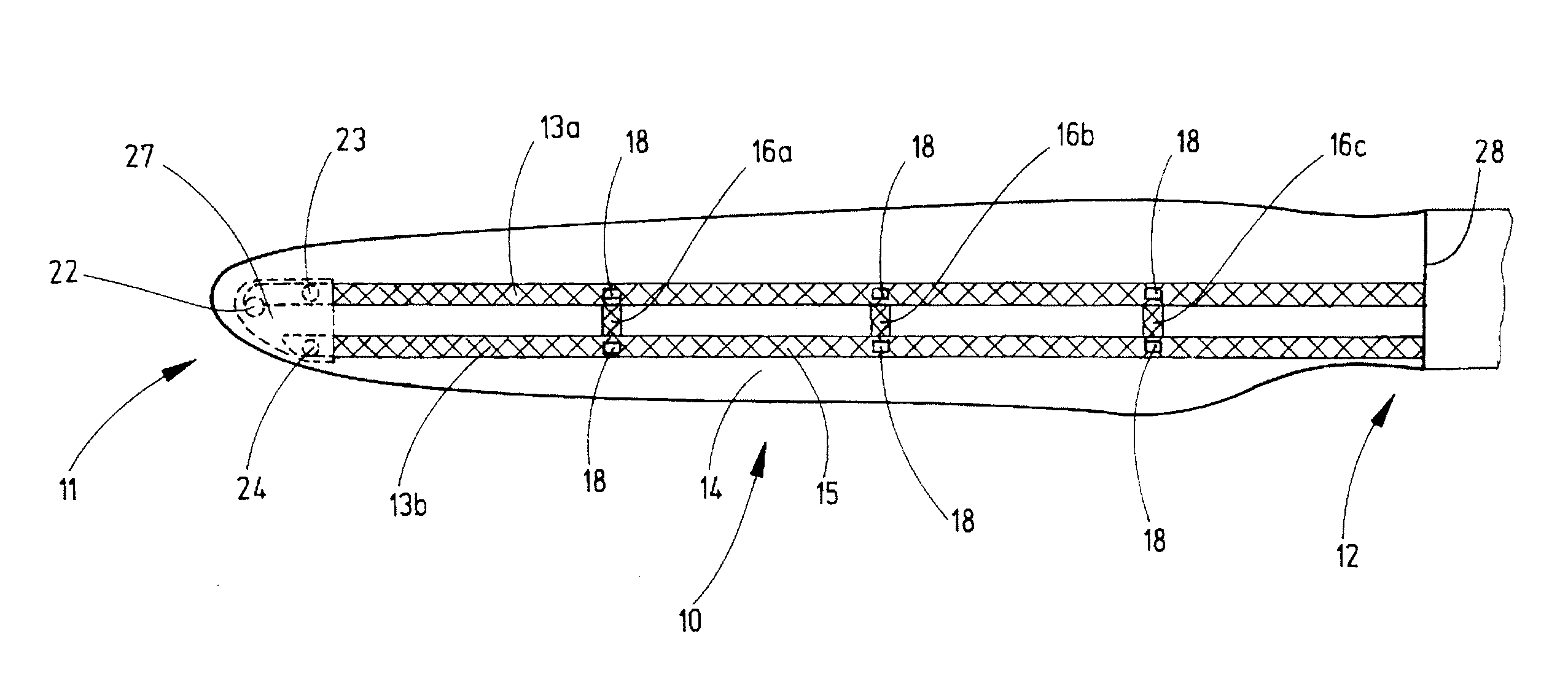
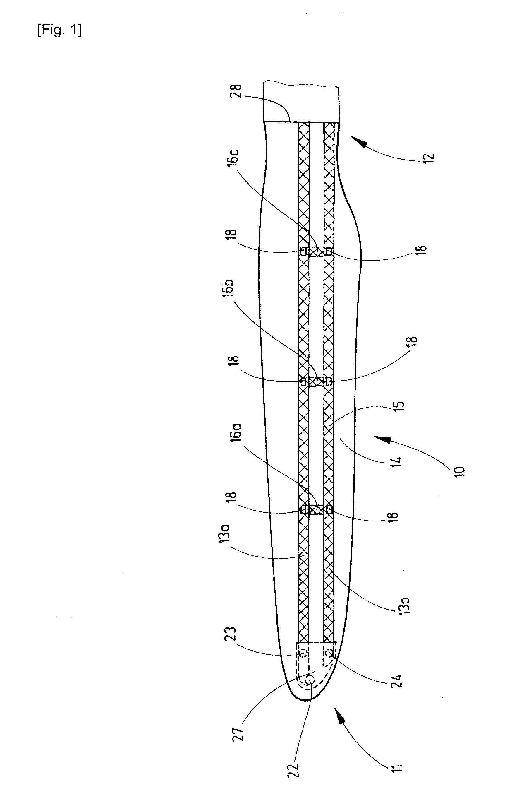
[0036]FIG. 1 shows a side view of a wind turbine blade 10 comprising a tip end area 11 and the root end area 12. The wind turbine blade 10 further has a lightning protection system comprising two metal foils 13a, 13b out of copper which extend continuously from the tip end area 11 of the blade 10 to the root end area 12 of the blade 10 along its longitudinal direction. The metal foils 13a, 13b are arranged at the outside of the outer blade layer 14 of the blade 10 and in radial direction behind spar caps 17a, 17b (see FIG. 3) which are located underneath the outer blade layer 14 except for the tip end area 11 of the blade 10. In the tip end area 11 of the blade 10, the metal foils 13a, 13b are arranged inside the blade 10 so that they are shown by a broken line. The metal foils 13a, 13b are only covered by a thin protective layer so that they can function as a receptor of a stroke of lightning. In this side view, the thin protective layer which usually covers the metal foils is not ...


PUM


Abstract

The invention relates to a wind turbine blade for a wind turbine, having a tip end area and a root end area, and a lightning protection system, said lightning protection system comprising at least one metal foil, wherein said metal foil extends continuously from the tip end area to the root end area of the blade and wherein the metal foil is arranged in proximity to the outer surface of the blade, so that the metal foil is adapted to function as a receptor of a stroke of lightning and as a down conductor.

Description

TECHNICAL FIELD[0001]The invention relates to a wind turbine blade for a wind turbine, wherein the wind turbine blade comprises a lightning protection system.BACKGROUND ART[0002]Due to their enormous size, wind turbines are highly prone to lightning strikes. In particular, the wind turbine blades being the component of the wind turbine reaching to the most distant point from the ground's surface and comprising weakly conductive material are at the highest risk of being struck by a lightning. In case of a lightning strike to the wind turbine blade, high currents in the surrounding material are generated, leading to excessive heating and damage of the material.[0003]For the above reasons, wind turbines, in particular wind turbine blades, are usually provided with a lightning protection system to protect them from lightning strikes. A common lightning protection system comprises several lightning receptors located at the surface of the blade and a cable functioning as a down conductor....

Claims


Application Information

Patent Timeline
IPC IPC(8): F03D11/00H02G13/00F03D80/00F03D80/30
CPCY02E10/721H02G13/00Y02E10/72F03D80/30F05B2240/307F03D1/0658F05B2240/30
Inventor FUJIOKA, HIDEYASUALWART, JENSCREMER, ANDREAS
Owner MITSUBISHI HEAVY IND LTD
Learn More