Controlling a Storage System

a storage system and control technology, applied in the field of data storage management, can solve the problems of affecting the life expectancy of the physical storage volume constituting the logical storage volume of the storage system, the inability to migrate data from one logical storage volume to another, and the inability to achieve data migration, etc., to achieve the effect of reducing the frequency of read and/or write operations, reducing the number of volumes, and reducing the number of read operations

Inactive Publication Date: 2013-06-13
IBM CORP
View PDF2 Cites 21 Cited by
  • Summary
  • Abstract
  • Description
  • Claims
  • Application Information

AI Technical Summary

Benefits of technology

[0017]modifying a grouping, said grouping assigning each of a plurality of controller nodes a disjunct group of the physical storage volumes to be controlled by said controller node, the modification increasing or decreasing the number of physical storage volumes controlled by one of said controller nodes, said one controller node currently controlling at least one of the physical storage volumes mapped to memory blocks of said one logical storage volume.
[0018]A ‘load parameter value violating a load parameter threshold value’ as used herein is a load parameter value lying below or exceeding said threshold value. Depending on the type of the load parameter threshold value, a measured parameter value lying below said threshold may be indicative of a higher load than specified in said threshold or a lower load than specified in this threshold. This is because many different parameters and corresponding thresholds are indicative of the I / O load of a particular logical and / or physical storage volume. Said features may be advantageous in that they allow dynamically determining and executing appropriate actions for preventing impending breaches of service level objectives (SLOB) and / or for correcting already occurred SLO breaches without triggering the migration of all data of a storage volume to another volume. Thus, a full volume migration and the corresponding data traffic within the storage system can in many cases be avoided completely. In a further advantageous aspect, existing storage volumes can be used more effectively and purchasing of additional storage volumes in order to guarantee a particular level of service may be avoided. In a further advantageous aspect, the life expectancy of the physical storage volumes constituting the logical storage volumes of the storage system may be prolonged as the total amount of data migrated from and to the storage volumes, and therefore the frequency of read and / or write operations per volume, is reduced. In a further advantageous aspect, embodiments of the invention are operable to fully automatically determine the one or more appropriate actions for increasing the performance of a volume or for decreasing the performance in order to free physical storage volumes for use by other logical volumes. This is not possible in many state of the art storage systems relying on a static configuration of the behavior of the storage system. By avoiding a full volume migration, i.e., a migration of the whole data content of a logical storage volume to another one, the storage network remains available for I / O requests of applications and is not clogged by the data traffic caused by the full volume migration.

Problems solved by technology

A drawback of this approach is that the complete amount of data of the source storage volume has to be transferred to the destination storage volume, thereby producing significant workload on the respective source and destination storage pools and in the storage network connecting the two.
In addition, oftentimes storage devices constituting the logical storage volumes of a storage pool are structured in such a way that migrating data from one logical storage volume to another is not possible in every case due to technical constraints relating to incompatible properties of the physical storage volumes.
In addition, organizational constraints for the migration of data exist as storage volumes and storage pools are commonly assigned specifically to groups or departments.

Method used


Image

  • Controlling a Storage System
  • Controlling a Storage System
  • Controlling a Storage System

Examples


Embodiment Construction

[0080]In the following, like numbered elements in these figures are either similar elements or perform an equivalent function.

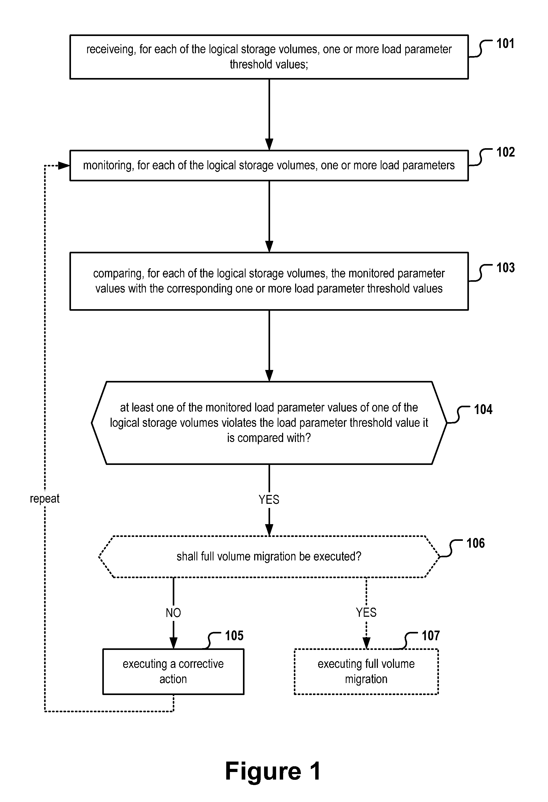
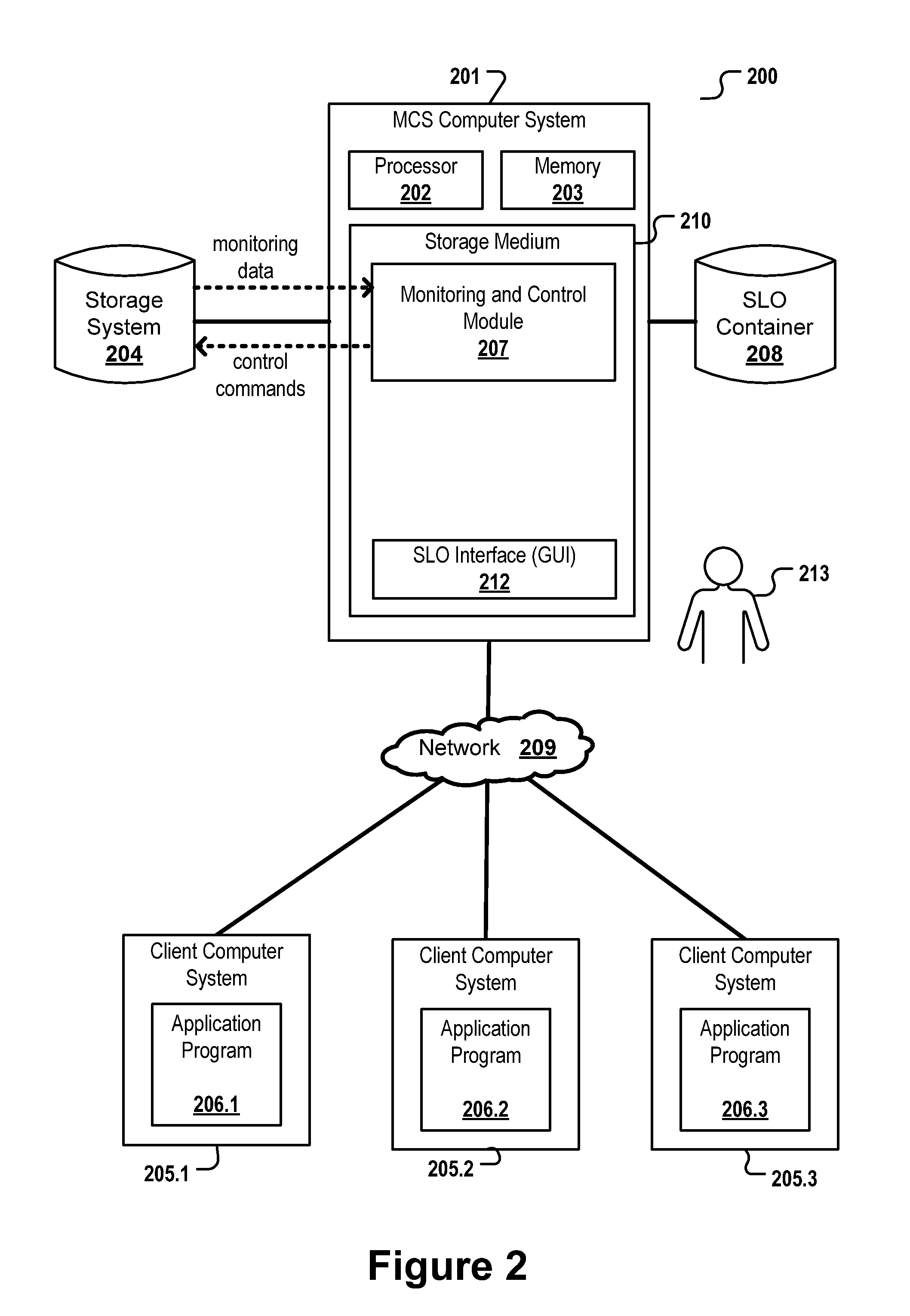
[0081]FIG. 1 shows a flowchart of a method to be executed by a monitoring and control module 207 as depicted in FIG. 2. The monitoring and control module 207 may thereby make use of monitoring capabilities provided by storage system 204. In a first receiving step 101, for each of the logical storage volumes of the storage system 204 one or more load parameter threshold values are received. For example, said threshold values are read from a configuration file stored in the storage system 204 or stored in the SLO container 208. In a monitoring step 102, for each of the logical storage volumes of the storage system, one or more load parameter values are measured. The measured load parameter values are compared in a succeeding comparison step 103 with the corresponding one or more load parameter threshold values. Said steps may be executed for each of the logical...


PUM


Abstract

A method, computer-readable storage medium and computer system for controlling a storage system, the storage system comprising a plurality of logical storage volumes, the method comprising: monitoring, for each of the logical storage volumes, one or more load parameters; receiving, for each of the logical storage volumes, one or more load parameter threshold values; comparing, for each of the logical storage volumes, the first load parameter values of said logical storage volume with the corresponding one or more load parameter threshold values; in case at least one of the first load parameter values of one of the logical storage volumes violates the load parameter threshold value it is compared with, automatically executing a corrective action.

Description

FIELD OF THE INVENTION[0001]The invention relates to the field of data storage management, and more particularly to the controlling of a storage system.BACKGROUND[0002]The demand for the automated management of an IT infrastructure, in particular the management and provision of storage space, has been constantly growing. The provision of storage space to a plurality of clients is typically based on a contract comprising a so called “service level agreement” (SLA) specifying the level of service a storage provider has agreed to provide to the respective client. Service level agreements can contain numerous service performance metrics which may be expressed in the form of service-level objectives. There is a need in the art for ensuring, in a cost-efficient manner, that storage volumes provided to the client devices are performing in accordance with the respective SLAs.[0003]Prior art approaches for avoiding performance-related SLA violations are typically based on moving all the data...

Claims


Application Information

Patent Timeline
Patent Type & Authority Applications(United States)
IPC IPC(8): G06F12/16G06F12/08
CPCG06F3/0604G06F3/0653G06F2201/81G06F11/3433G06F11/3485G06F3/0683
Inventor BOLIK, CHRISTIANFIEBRICH-KANDLER, UWENOLL, DIETMAR
Owner IBM CORP
Why Eureka
Try Eureka