Band-pass filter
a bandpass filter and filter technology, applied in waveguide devices, electrical equipment, resonators, etc., can solve the problems of achieving desired frequency characteristics, achieve excellent characteristics, prevent or minimize unnecessary electromagnetic field coupling, and increase capacitors. the effect of capacitan
- Summary
- Abstract
- Description
- Claims
- Application Information
AI Technical Summary
Benefits of technology
Problems solved by technology
Method used
Image
Examples
first preferred embodiment
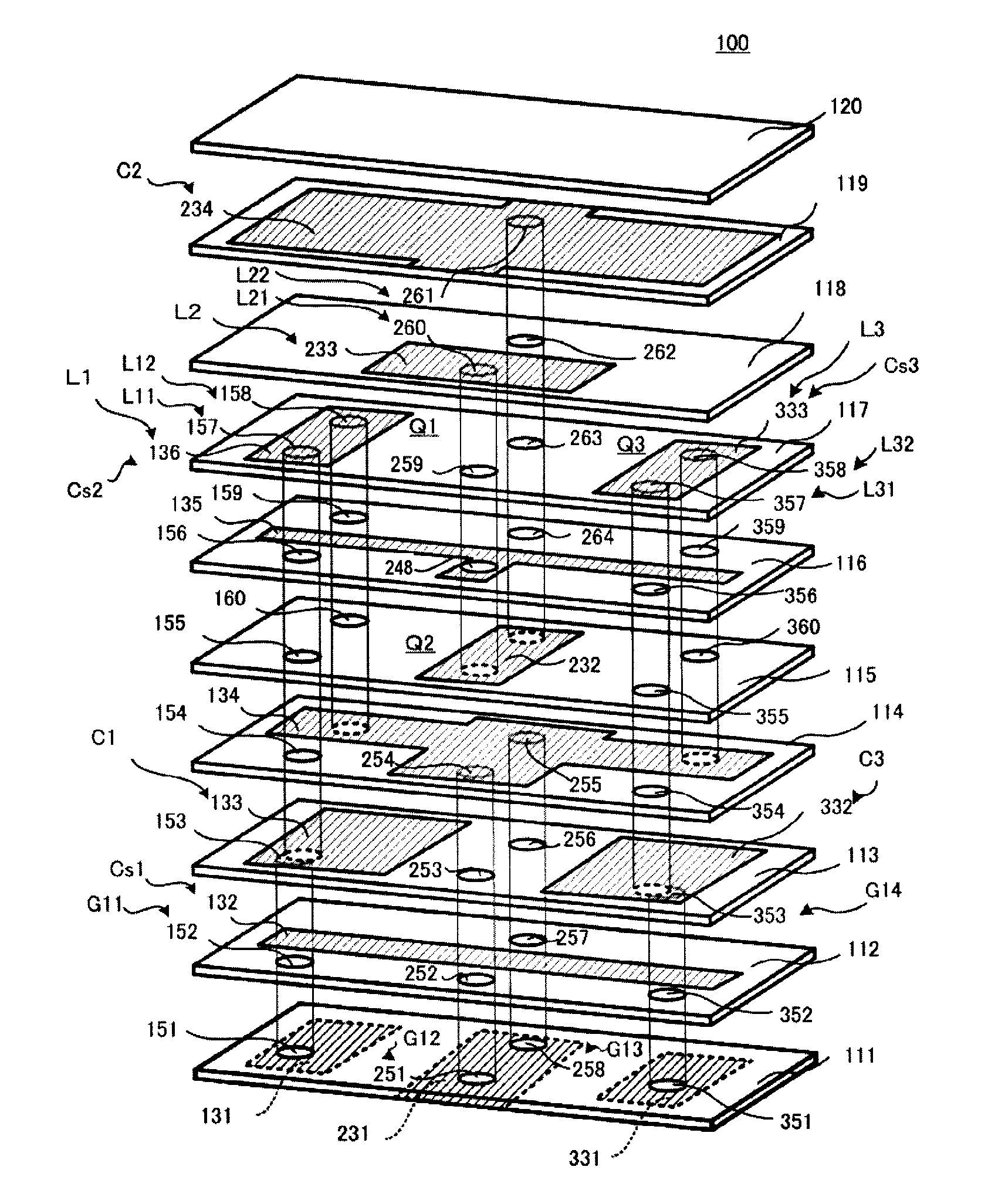
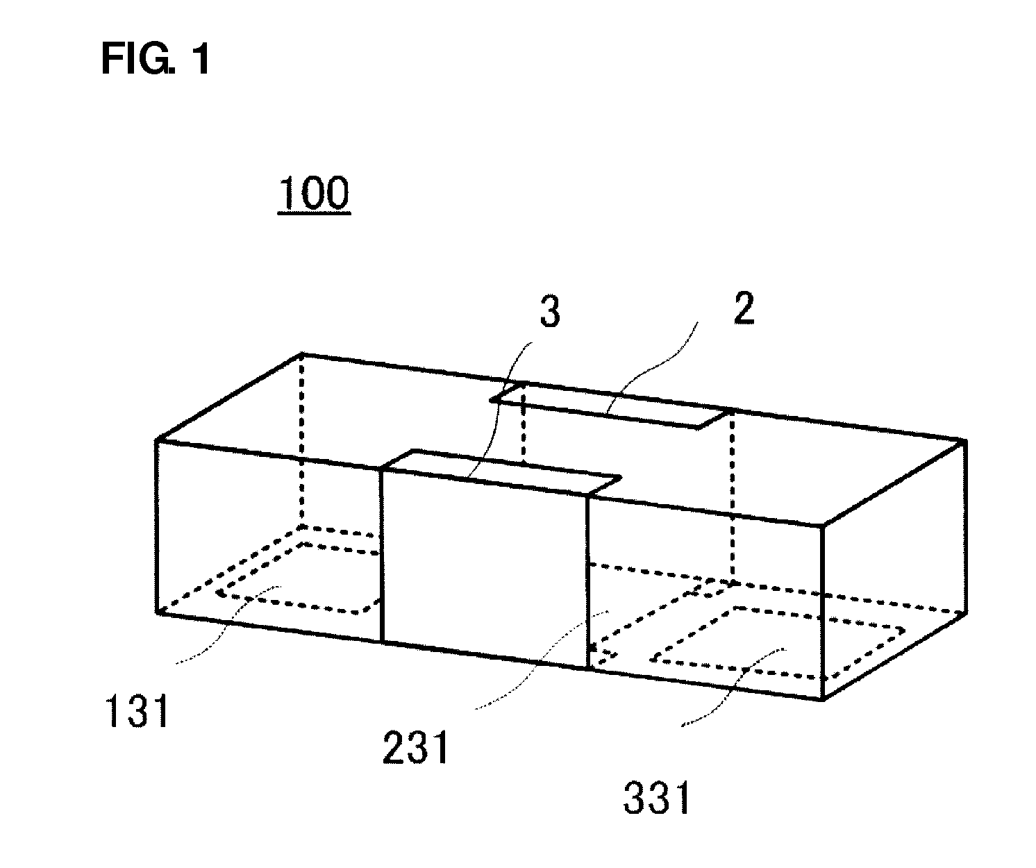
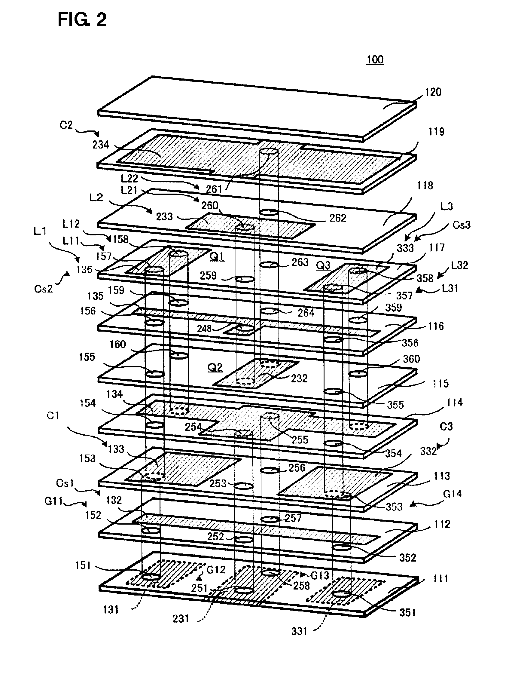
[0040]A band-pass filter according to a first preferred embodiment of the present invention will now be described with reference to FIGS. 1 to 3. FIG. 1 is an external perspective view of the band-pass filter according to the first preferred embodiment. FIG. 2 is an exploded perspective view of the band-pass filter according to the first preferred embodiment, in which ground terminals 2 and 3 are omitted. FIG. 3 is an equivalent circuit diagram of the band-pass filter according to the first preferred embodiment.
[0041]Referring to FIG. 2, a band-pass filter 100 according to the first preferred embodiment preferably includes a multilayer body in which multiple dielectric layers are stacked. Via electrodes that penetrate through certain electrodes and dielectric layers described below in the stacking direction are provided in the dielectric layers.
[0042]The band-pass filter 100 preferably includes three LC resonators, for example. A first-stage LC resonator Q1 includes an input electro...
second preferred embodiment
[0076]FIG. 5 is an exploded perspective view of a band-pass filter 200 according to a second preferred embodiment of the present invention. Since the external perspective view of the band-pass filter 200 is the same or substantially the same as the external perspective view of the first preferred embodiment shown in FIG. 1, it is not shown. The ground terminals 2 and 3 outside the multilayer body are omitted in FIG. 5.
[0077]Referring to FIG. 5, the band-pass filter 200 of the second preferred embodiment preferably includes three-stage LC resonators, as in the first preferred embodiment.
[0078]The second preferred embodiment differs from the first preferred embodiment in that the inductor of the second-stage LC resonator includes a via inductor, instead of the loop inductor including the via inductors and the line electrode. The remaining structure of the second preferred embodiment is preferably the same or substantially the same as that of the first preferred embodiment.
[0079]The st...
third preferred embodiment
[0084]FIG. 6 and FIG. 7 show a band-pass filter 300 according to a third preferred embodiment of the present invention. FIG. 6 is an external perspective view of the band-pass filter 300. FIG. 7 is an exploded perspective view of the band-pass filter 300. Input and output terminals 4, 6, 7, and 9 and ground terminals 5 and 8, which are provided outside the multilayer body, are omitted in FIG. 7.
[0085]Referring to FIG. 7, the band-pass filter 300 of the third preferred embodiment preferably includes three-stage LC resonators, as in the first preferred embodiment.
[0086]The third preferred embodiment differs from the first preferred embodiment in that the resonator capacitor of the first-stage LC resonator is arranged on one main surface of the multilayer body. The resonator capacitor of the second-stage LC resonator is arranged on one main surface of the multilayer body in the first preferred embodiment. In the band-pass filter 300 of the third preferred embodiment, input and output e...
PUM
 Abstract
Description
Claims
Application Information
 - R&D
- Intellectual Property
- Life Sciences
- Materials
- Tech Scout
- Unparalleled Data Quality
- Higher Quality Content
- 60% Fewer Hallucinations
Browse by: Latest US Patents, China's latest patents, Technical Efficacy Thesaurus, Application Domain, Technology Topic, Popular Technical Reports.
© 2025 PatSnap. All rights reserved.Legal|Privacy policy|Modern Slavery Act Transparency Statement|Sitemap|About US| Contact US: help@patsnap.com


