Hybrid bi-directional DC contactor and method of controlling thereof

a technology of bi-directional dc contactor and hybrid dc contactor, which is applied in the direction of electromagnetic relay, electrical apparatus, electrical relay details, etc., can solve the problems of increasing the production cost of existing hybrid dc contactors, the design and control of such hybrid dc contactors, and the inability to determine the separation between moving and fixed contacts

Inactive Publication Date: 2013-06-20
EATON CORP
View PDF3 Cites 34 Cited by
  • Summary
  • Abstract
  • Description
  • Claims
  • Application Information

AI Technical Summary

Problems solved by technology

While existing hybrid DC contactors do function to provide a bypass path to the mechanical contacts, there are drawbacks to the design and control of such hybrid DC contactors.
One such drawback to existing hybrid DC contactors is that, when bypassing the main contacts, the separation between the moving and fixed contacts cannot be determined.
Not knowing the separation, the sold state device is left closed for a fixed but long enough delay to ensure interruption of the current.
This oversizing of the IGBT switch increases the production cost of existing hybrid DC contactors.
Another drawback to existing drawback hybrid DC contactors is that the switching time of the contactor is prolonged enough that the contacts may still be exposed to an undesirable “restrike” of arcing.
Still another drawback of the prior art hybrid DC contactors is that, if there is restrike of the arc, there is no capability to know the condition and this could result in the burning out of the contactor.
Still another drawback to existing drawback hybrid DC contactors is that they do not provide galvanic isolation, which is desirable in some implementations of hybrid DC contactors.
Still another drawback is that the existing design of hybrid DC contactors is not suitable for bidirectional currents.

Method used


Image

  • Hybrid bi-directional DC contactor and method of controlling thereof
  • Hybrid bi-directional DC contactor and method of controlling thereof
  • Hybrid bi-directional DC contactor and method of controlling thereof

Examples


Embodiment Construction

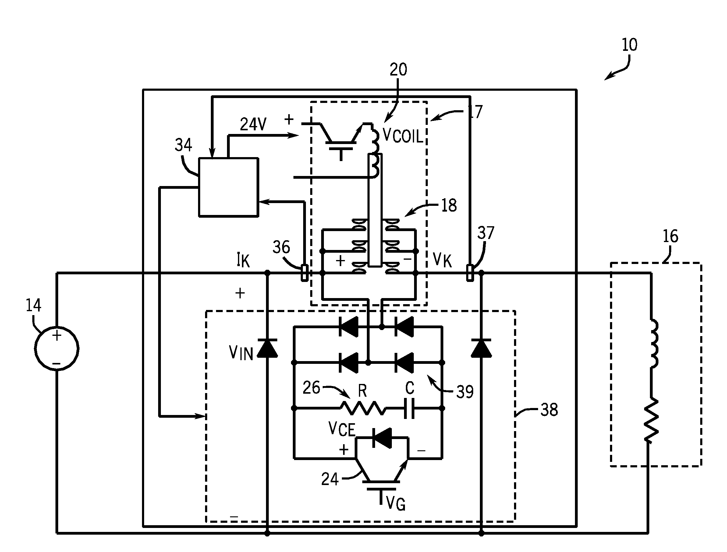
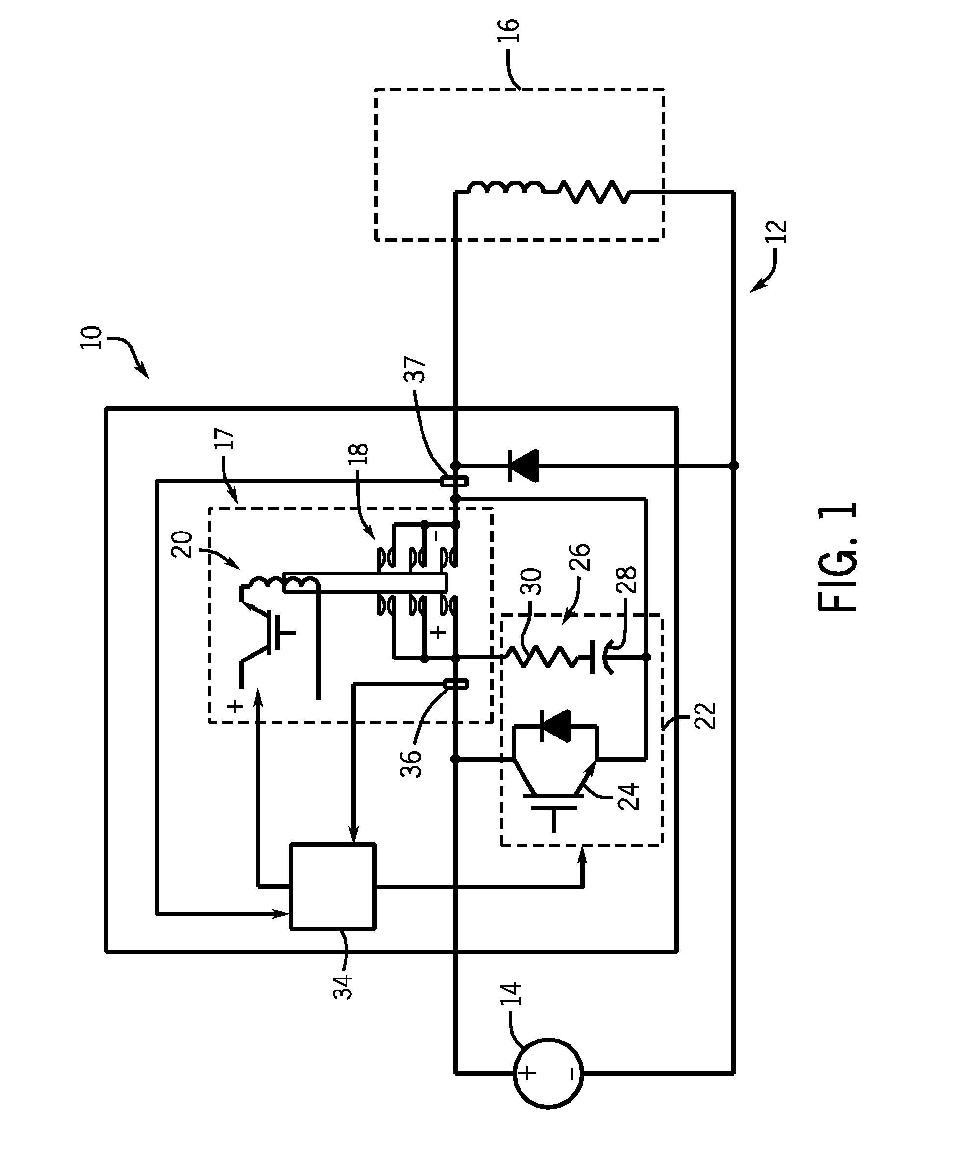
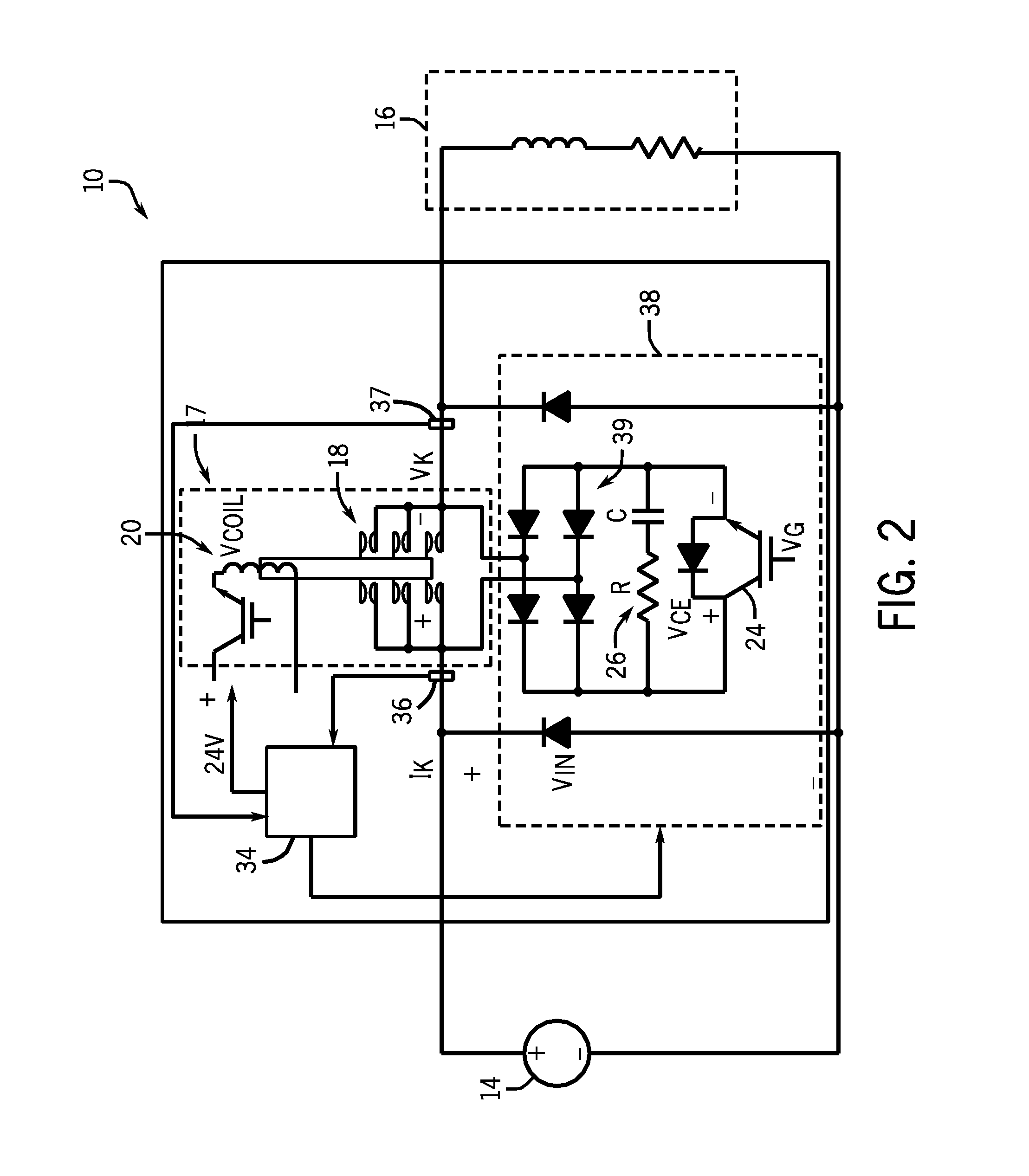
[0022]The embodiments of the invention set forth herein relate to a system and method for controlling operation of a hybrid DC contactor. A hybrid DC contactor is provided that includes a semiconductor switch connected in parallel to the plurality of contacts, so as to provide a parallel current path that diverts current away from the plurality of main contacts when the semiconductor switch is turned on and the power to the coil is de-energized (the current will not go through the IGBT when the contacts are closed). When the main contacts are desired to be opened, and start to open, a controller associated with the hybrid DC contactor detects an arc voltage across the main contacts. After the arc voltage is detected, the controller institutes a delay period before then providing a gate signal to the semiconductor switch to cause the semiconductor switch to pulse on for a pre-determined period of time so as to route all the current to the semiconductor switch. Upon pulsing the semico...


PUM


Abstract

A hybrid DC contactor includes contacts that provide a first current path between a DC power source and a load, an electromagnetic coil to position the contacts, a semiconductor switch in parallel with contacts that, when turned on, provides a second parallel current path that diverts current away from the contacts when the main contacts are being opened in either direction. A controller is provided to terminate power to the electromagnetic coil to open the contacts, detect an arc voltage across the contacts as the contacts open, provide a gate signal to the semiconductor switch to pulse the switch on for a pre-determined period of time to route current to the semiconductor switch, measure a current through the contacts and, if current is present through the contacts, then provide another gate signal to the semiconductor switch to pulse the switch on again so as to route current thereto.

Description

BACKGROUND OF THE INVENTION[0001]The present invention relates generally to hybrid direct current (DC) contactors and, more particularly, to a system and method for controlling operation of a hybrid DC contactor that improves performance of the hybrid contactor.[0002]Electro-mechanical contactors are used in a variety of environments for turning on and off a power source to a load electrically. The contactors include movable contacts and fixed contacts. The movable contacts are connected to an electromagnet and are controlled to selectively turn on or off power from the source to the load. The contacts are typically maintained in an open position by way of a spring and are caused to translate to a closed position when power to the electromagnet's coil is applied.[0003]When electro-mechanical contactors are used for interrupting AC currents, it is recognized that there is always a time when the current becomes zero. Electro-mechanical contactors can thus interrupt current at the zero...

Claims


Application Information

Patent Timeline
Patent Type & Authority Applications(United States)
IPC IPC(8): H01H51/06
CPCH01H47/18H01H50/045H01H47/32
Inventor BHAVARAJU, VIJAYZHAO, TIEFUTHEISEN, PETER J.
Owner EATON CORP
Why Eureka
Try Eureka