Calculation apparatus and calculation method of magnetic field, electron density and electron temperature

a calculation apparatus and magnetic field technology, applied in the field of calculating the magnetic field profile, the electron temperature profile and the electron temperature can solve the problems of difficult to simultaneously obtain the relativistic effect cannot be ignored in a high-temperature plasma, and the difficulty of simultaneously obtaining the magnetic field profile and the electron density profile within the plasma

Inactive Publication Date: 2013-06-20
JAPAN ATOMIC ENERGY AGENCY INDEPENDANT ADMINISTRATIVE CORP
View PDF1 Cites 14 Cited by
  • Summary
  • Abstract
  • Description
  • Claims
  • Application Information

AI Technical Summary

Benefits of technology

[0013]A contribution of the electron temperature (relativistic effect) was small in terms of interaction between the plasma and the laser beam (electromagnetic radiation) and had been therefore ignored so far. The relativistic effect cannot, however, be ignored in a high-temperature plasma in which the nuclear fusion reaction occurs. Namely, on the occasion of obtaining the magnetic field profile and the electron density profile from the measured values of the polarimeter, it is required that the relativistic effect is taken into consideration, and there is a necessity for previously obtaining the electron temperature profile by an electron temperature measuring apparatus (a Tho...

Problems solved by technology

Variations (the rotation and the ovalization) of the polarization plane of the laser beam have information on the magnetic field profile and information on the electron density profile on a path of the laser beam, however, it is difficult to simultaneously obtain both of the magnetic field profile and the elect...

Method used


Image

  • Calculation apparatus and calculation method of magnetic field, electron density and electron temperature
  • Calculation apparatus and calculation method of magnetic field, electron density and electron temperature
  • Calculation apparatus and calculation method of magnetic field, electron density and electron temperature

Examples


operational example

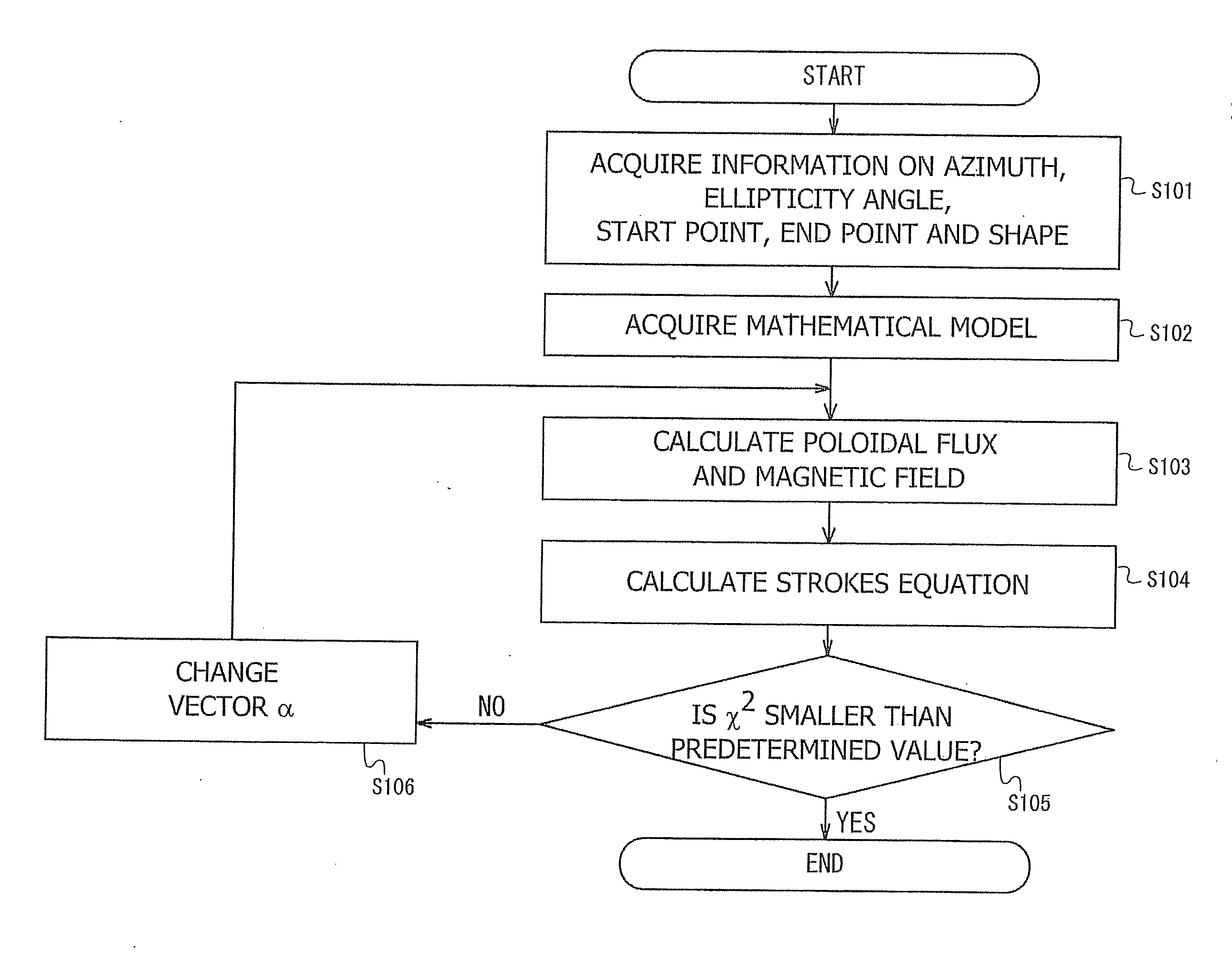
[0056]FIG. 4 is a diagram illustrating an example of an operation flow of the calculation apparatus 100.

[0057]The first acquiring unit 102 of the calculation apparatus 100 acquires the azimuth and the ellipticity angle of the polarized light beam of the laser that are measured by the polarimeter etc, the position information on the start point and the end point of the laser beam, the wavelength of the laser beam and the position information on the border of the plasma area from the storage unit 110 (S101). The first acquiring unit 102 acquires the azimuths, the ellipticity angles and the position information on the start points and the end points with respect to a plurality of lines of sight. The first acquiring unit 102 acquires the azimuths and the ellipticity angles at the start points and the end points of the respective lines of sight. The azimuth and the ellipticity angle of the polarized light beam of the laser at the start point are acquired as, e.g., the azimuth and the ell...

specific example

[0087]FIGS. 5, 6 and 7 are diagrams illustrating specific examples of calculation results of the calculation apparatus in the embodiment. On the assumption of the tokamak plasma, the calculation apparatus in the embodiment obtains the magnetic field profile, the electron density profile and the electron temperature profile. FIG. 5 is a graph illustrating an example of the magnetic field profile. In the graph of FIG. 5, the axis of abscissas indicates the radial direction in the cylindrical coordinate system, while the axis of ordinates indicates the magnetic field. FIG. 6 is a graph illustrating an example of the electron density profile. In the graph of FIG. 6, the axis of abscissas indicates the radial direction in the cylindrical coordinate system, while the axis of ordinates indicates the electron density. FIG. 7 is a graph illustrating an example of the electron temperature profile. In the graph of FIG. 7, the axis of abscissas indicates the radial direction in the cylindrical ...

embodiment

Operation and Effect of Embodiment

[0088]Only the azimuth has hitherto been focused in the case of estimating the profile of the physical quantity within the plasma from the data of the polarimeter. If using an approximation of the Faraday effect, the azimuth takes a value obtained by linearly integrating a product of the density and the magnetic field component parallel to the line of sight on the line of sight. Accordingly, the electron density profile is calculated from the azimuth on the assumption that the magnetic field profile is already known (e.g., the magnetic field is already known in the helical type nuclear fusion plasma), or alternatively the magnetic field profile is calculated from the azimuth on the assumption that the electron density profile is already known from other types of electron density profile measuring apparatuses (an interferometer, a reflectometer, a Thomson scattering diagnostics, etc). Further, a linear integral quantity of the density on the line of ...


PUM


Abstract

A calculation apparatus comprising: an acquiring unit to acquire an azimuth and an ellipticity angle of a polarization plane of a laser beam passing through a plasma; and a calculation unit to calculate at least one of a magnetic field profile, an electron density profile and an electron temperature profile in the plasma on the basis of the azimuth and the ellipticity angle.

Description

CROSS-REFERENCE TO RELATED APPLICATIONS[0001]This application claims the benefit of Japanese Application No. 2011-274818, filed Dec. 15, 2011, in the Japanese Intellectual Property Office, the disclosure of which are incorporated herein by reference.BACKGROUND OF THE INVENTION[0002]1. Field of the Invention[0003]The present invention relates to a method of calculating a magnetic field profile, an electron density profile and an electron temperature profile within plasma.[0004]A method of making use of polarization of a laser beam exists as a method of measuring in a non-contact manner the magnetic field profile within the plasma in the nuclear fusion plasma. When a linearly polarized laser beam enters the plasma, a polarization plane thereof rotates and gets ovalized by dint of interaction between the plasma and the laser beam (electromagnetic radiation). In this method, the magnetic field profile is calculated based on an angle of the rotation of the polarization plane of the laser...

Claims


Application Information

Patent Timeline
IPC IPC(8): G06F15/00G06F17/50G01R29/00G01K13/00G01R33/12
CPCG01R19/0061G06F15/00G01K13/00G06F2217/16G01R29/00G06F17/5009G01R33/0064G01R33/1215G06F30/20G06F2111/10Y02E30/10
Inventor IMAZAWA, RYOTA
Owner JAPAN ATOMIC ENERGY AGENCY INDEPENDANT ADMINISTRATIVE CORP
Why Eureka
Try Eureka