
System and method for an acoustic monitor self-test

a self-testing and monitor technology, applied in the field of machine condition monitoring, acoustics, digital signal processing, can solve the problems of reducing the sensitivity of the detector, false alarms in nearby detectors, and reducing the output of the emitter to the lowest level

Inactive Publication Date: 2013-06-27
UTC FIRE & SECURITY AMERICAS CORPORATION INC
View PDF6 Cites 90 Cited by
  • Summary
  • Abstract
  • Description
  • Claims
  • Application Information

AI Technical Summary

Benefits of technology

The invention is a system and method for self-testing an acoustic monitor. The system includes a memory to store a reference acoustic power, a digital signal processor (DSP) to compute the acoustic power spectrum of background noise in a frequency range of about 20 Hz to about 80 kHz, and a microphone with analog signal conditioning circuitry to receive an acoustic test signal. The system also includes a processor to compare the measured acoustic power with a calculated acoustic power, which takes into account the reference acoustic power and an attenuation level. The technical effects of this invention include improved accuracy and reliability in measuring acoustic power and facilitating self-tests of an acoustic monitor.

Problems solved by technology

Since the detector is exposed to the environment, it is possible that ice or dust build-up on the microphone may attenuate the acoustic signal, thus reducing the sensitivity of the detector and possibly preventing an alarm from occurring during an actual gas leak.
It has been demonstrated that this method of self-test has the potential to cause a false alarm in nearby detectors of similar design.
Other prior art detectors do not have the ability to move the acoustic test signal to a relatively inactive portion of the power spectrum, or even know where that is, so they cannot reduce the emitter output to the lowest level necessary to perform the self-test.
Another serious limitation of prior art detectors is that their critical safety function must be disabled during the self-test, since, without knowing the power spectrum of the signal received by the microphone, an acoustic test signal is indistinguishable from a signal produced by a gas leak.
If the background noise is not detected, or if it has dropped significantly and unexpectedly, then the detector indicates a fault.
But the detector must have a very high sensitivity, otherwise this method of self-test will not work in quiet environments.

Method used


Image

  • System and method for an acoustic monitor self-test
  • System and method for an acoustic monitor self-test

Examples


Embodiment Construction

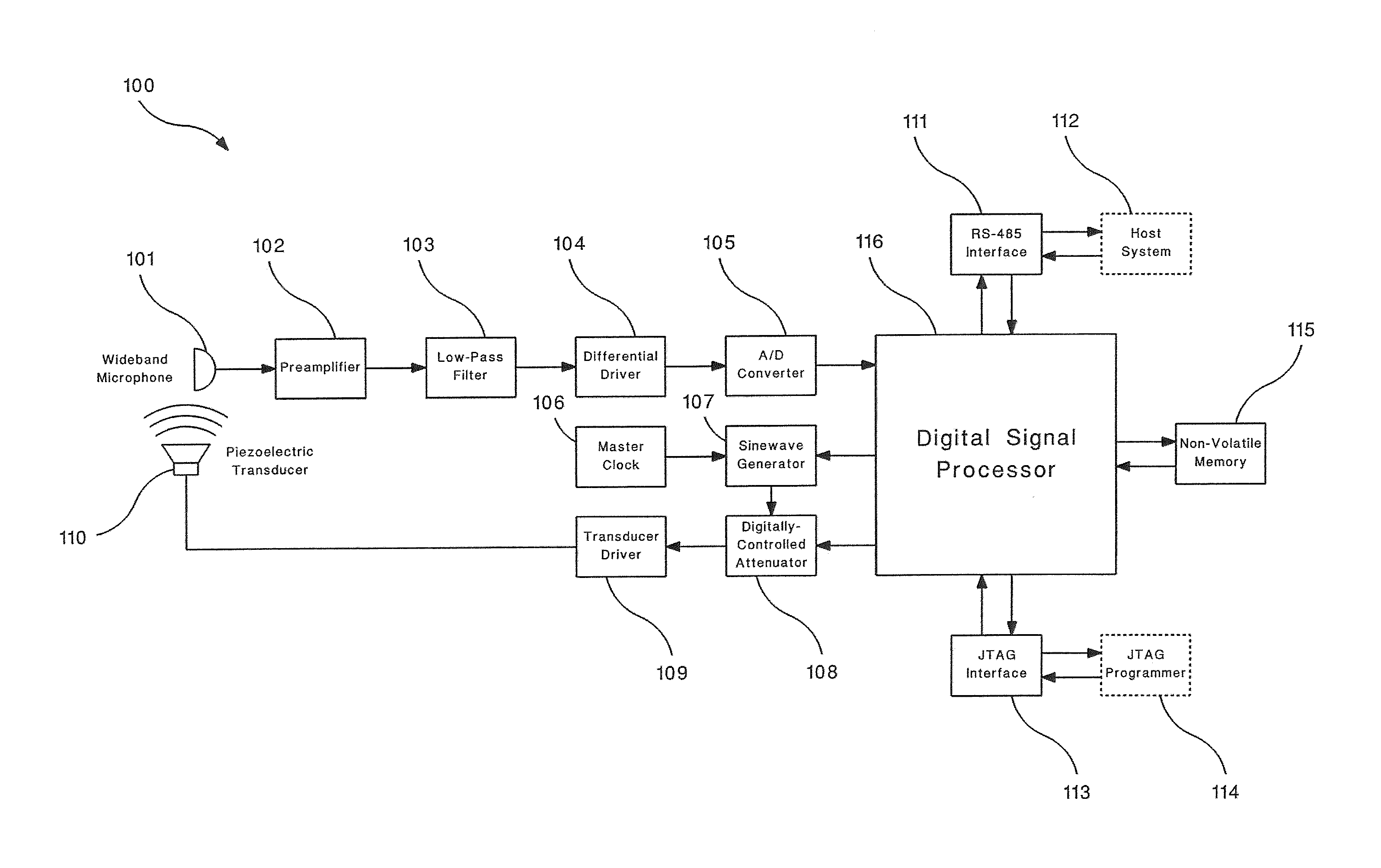
[0011]Embodiments of an acoustic monitor having an acoustic signal source for implementing a self-test are described herein. The acoustic monitor generates acoustic test signals having a frequency associated with a relatively inactive portion of the power spectrum and a sound pressure level providing an optimum signal-to-noise ratio (for example, signal-to-noise ratio exceeding a minimum threshold) at the test frequency. The acoustic test signal is determined by the digital signal processor, based on the power spectrum of the background noise, in order to provide differentiation between the acoustic test signal and the background noise. The acoustic monitor includes a digital signal processor (DSP) to continuously compute the power spectrum of an acoustic signal received by a microphone. The processor also performs, in some non-limiting examples, communication with a host system or human operator, control of the acoustic monitor, and acoustic self-test periodically during operation....


PUM


Abstract

A system for self-testing an acoustic monitor includes a memory that stores a reference acoustic power of a reference acoustic signal; a digital signal processor (DSP) that computes a real-time acoustic power spectrum of background noise in a frequency range of about 20 Hz to about 80 kHz; a microphone including analog signal conditioning circuitry that receives an acoustic test signal at a test frequency and sound pressure level (SPL), the SPL including an attenuation level; and a processor that compares a measured acoustic power at the test frequency with a calculated acoustic power of the acoustic test signal, the calculated acoustic power including the reference acoustic power and the attenuation level; where the acoustic monitor includes the DSP in signal communication with the microphone.

Description

FIELD OF INVENTION[0001]The subject matter disclosed herein relates generally to the fields of machinery condition monitoring, acoustics, and digital signal processing, and more particularly, to an acoustic monitor which periodically generates an acoustic test signal, having a known frequency and sound pressure level (SPL), for self-testing the acoustic monitor by computing the real-time power spectrum of the acoustic test signal while preventing other nearby acoustic monitors from alarming.DESCRIPTION OF RELATED ART[0002]Industrial operations, such as well drilling, oil production, oil refining, gas production, and petrochemical manufacturing, utilize piping to move a wide variety of flammable hydrocarbon gases and liquids under high pressure. These facilities also employ various types of pressure vessels, such as chemical reactors, heat exchangers, and storage tanks, which also may contain these potentially explosive gases and liquids. The piping and pressure vessels must be conti...

Claims


Application Information

Patent Timeline
IPC IPC(8): G01F23/296G06F19/00
CPCG01N29/30G01N29/14
Inventor HERMANN, THEODORE M.RADOMSKI, JAMES V.
Owner UTC FIRE & SECURITY AMERICAS CORPORATION INC
Learn More