
Microelectromechanical system

a micro-electromechanical and micro-electromechanical technology, applied in the direction of acceleration measurement using interia force, devices using electric/magnetic means, instruments, etc., can solve the problem that the distance between the detection mass and the substrate or between the two sensor electrodes cannot be accurately determined in the initial neutral state neither, so as to facilitate the production of the slit, relieve material stress, and affect the stress relief of the driving and/or detection mass

Inactive Publication Date: 2013-07-04
HANKING ELECTRONICS LTD
View PDF8 Cites 2 Cited by
  • Summary
  • Abstract
  • Description
  • Claims
  • Application Information

AI Technical Summary

Benefits of technology

The patent text describes a way to reduce distortion and material stresses in a driving and detection mass, which can also improve the performance of the mass. This is achieved by applying slits to the mass in a way that eliminates distortions and relieves stresses. The slits can be aligned in different directions and can intersect each other. The rigidity of the mass is not negatively affected by the slits. The slits can be deep enough to extend through the mass or only partially correspond to its thickness. Additionally, holes can be provided in the mass to further reduce weight and relieve stresses. The invention provides a way to improve the performance and functionality of the driving and detection mass.

Problems solved by technology

If the detection mass has become deformed due to material stresses that remain from the production process, for example, or due to temperature effects, then the distance between the detection mass and the substrate or between the two sensor electrodes will not be able to be accurately determined in the initial neutral state nor in case of a deflection of the detection mass.

Method used


Image

  • Microelectromechanical system
  • Microelectromechanical system
  • Microelectromechanical system

Examples


Embodiment Construction

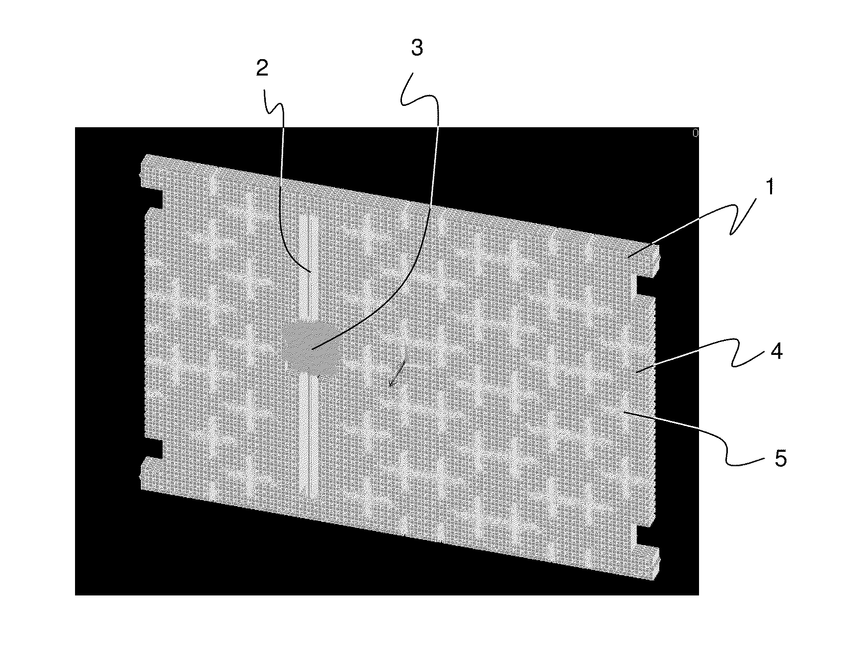
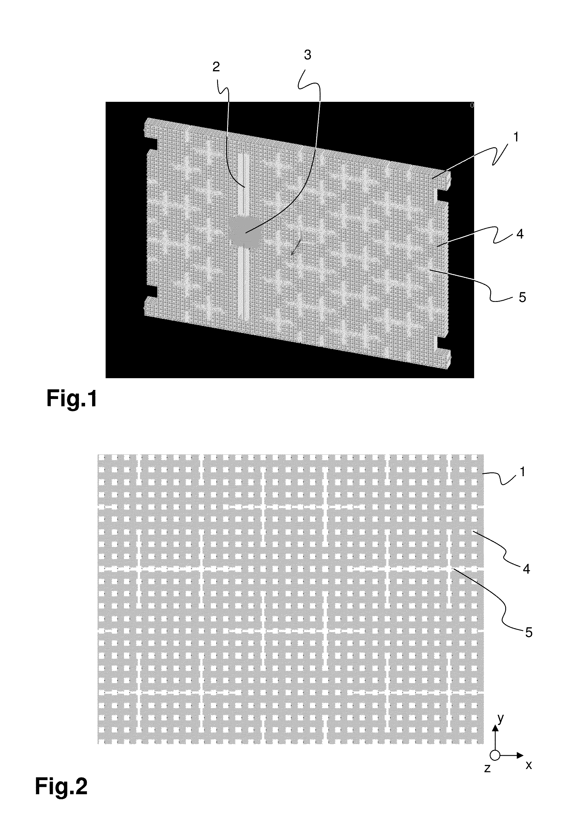
[0028]FIG. 1 shows a perspective view of a driving and detection mass 1 of a microelectromechanical system. The driving and detection mass 1 serves for detecting accelerations, for example, wherein the driving and detection mass 1 rotates about a rotational axis. The driving and detection mass 1 is shown here as a single, common mass. The invention, however, is advantageous for separate masses as well, wherein each mass fulfills only its own task, i.e. the driving mass drives the system and is deflected due to a Coriolis force in the event of acceleration of the system, and the detection mass, which in this case is deflected with the driving mass and serves for determining the magnitude of the deflection or acceleration. The shape of the driving and detection mass 1 can, of course, also be implemented differently.

[0029]The rotational axis is implemented by a torsional spring 2 rotatably attaching the driving and detection mass 1 to an anchor 3. The anchor 3 is shown only in a rough ...


PUM


Abstract

A microelectromechanical system for detecting accelerations about or along an X-axis, Y-axis, and / or Z-axis, having a substrate and having a driving mass and a detection mass (1) disposed parallel to the substrate in an X-Y plane and mounted displaceably relative to the substrate. At least one slit (5) is disposed in the driving and / or detection mass (1) for compensating for distortions due to residual material stresses in the driving and / or detection mass (1).

Description

CROSS REFERENCE TO RELATED APPLICATIONS[0001]The application claims the benefit of German Application Serial No. 10 2011 057 169.8, entitled “Mikroelektromechanisches System”, filed on Dec. 29, 2011, the subject matter of which is incorporated herein by reference.BACKGROUND[0002]A. Technical Field[0003]The present invention relates to a microelectromechanical system for detecting accelerations about or along an X-axis, Y-axis, and / or Z-axis, having a substrate and having a driving mass and a detection mass disposed parallel to the substrate in an X-Y plane and mounted displaceably relative to the substrate.[0004]B. Background of the Invention[0005]An MEMS resonator structure is known from WO 2009 / 079188 A1, wherein a driving and detection mass is disposed parallel to a substrate in an X-Y plane and is mounted displaceably relative to the substrate. The driving and detection mass comprises zones having different rigidity. It is thereby made possible that the driving and detection mas...

Claims


Application Information

Patent Timeline
IPC IPC(8): G01C19/5712
CPCG01C19/5712
Inventor BERTINI, LORENZO
Owner HANKING ELECTRONICS LTD
Learn More