

Contactless electricity supply device
a technology of electricity supply device and contactless, which is applied in the direction of rail device, charging station, transportation and packaging, etc., can solve the problems of inability to accurately detect on a basis of change in transmission efficiency a foreign object, and the transmission efficiency can be lowered
- Summary
- Abstract
- Description
- Claims
- Application Information
AI Technical Summary
Benefits of technology
Problems solved by technology
Method used
Image

Examples
first embodiment
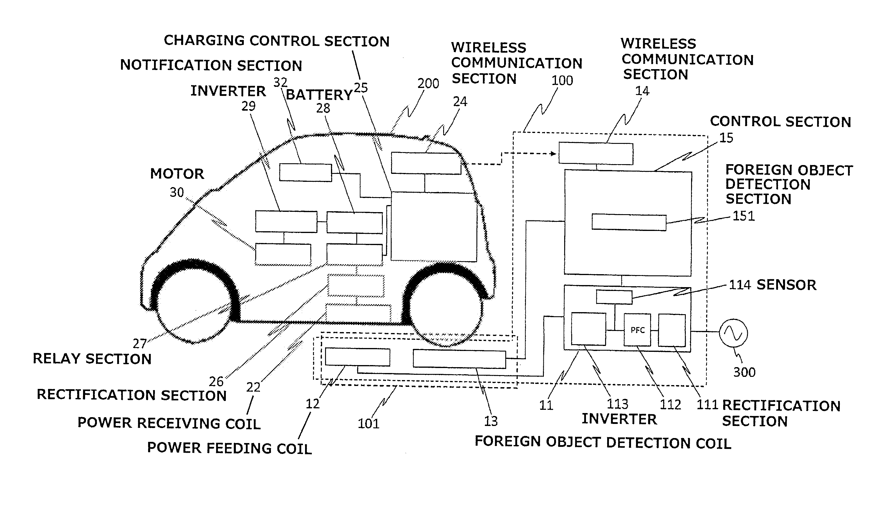
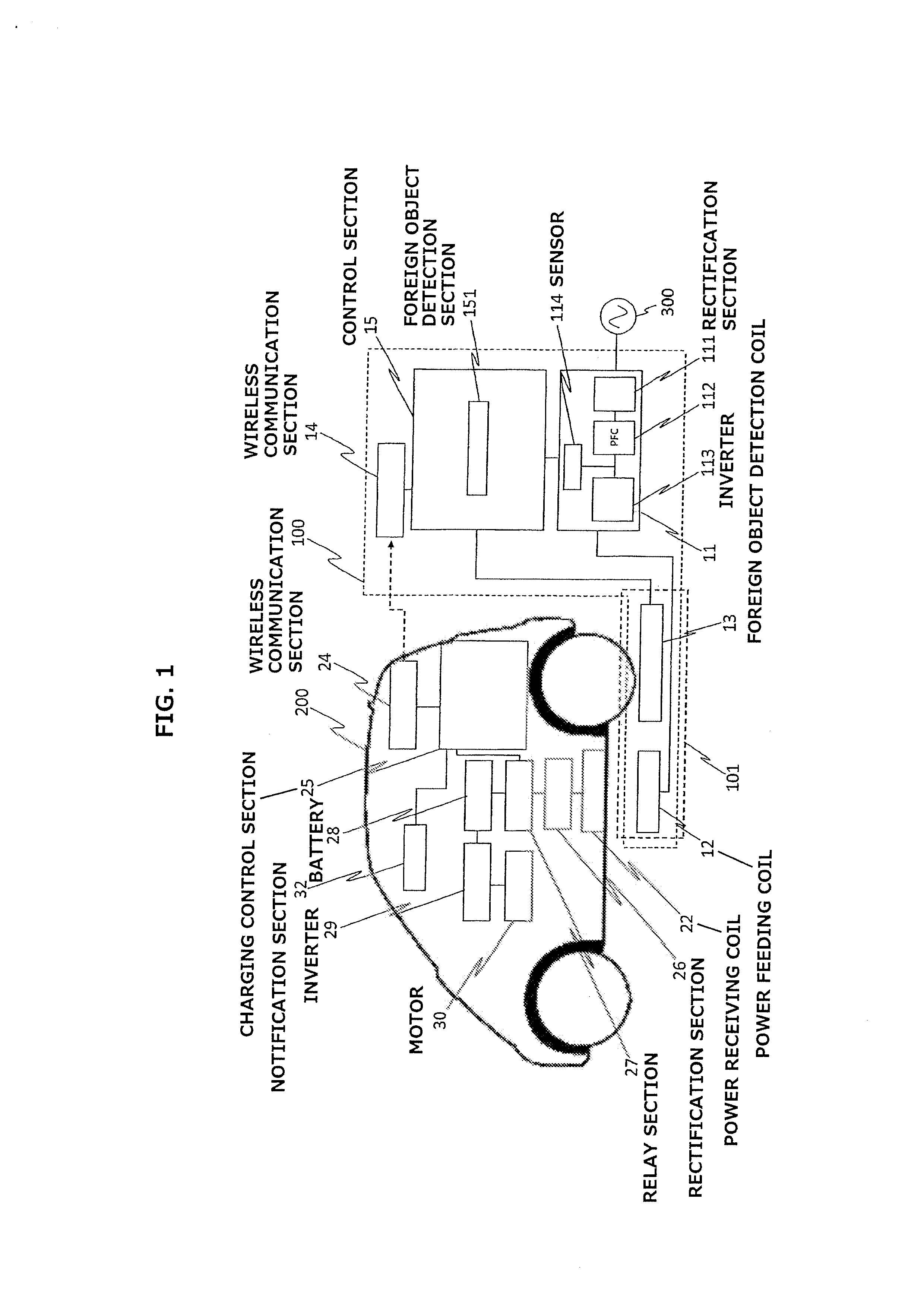
[0022]FIG. 1 is a block diagram of a contactless electricity supply system including a vehicle 200 and an electricity supply device 100, which includes a contactless electricity supply device according to an embodiment of the present invention. A vehicle-side unit of the contactless electricity supply device of the embodiment is mounted on an electric vehicle, but may be mounted on a hybrid electric vehicle or the like.
[0023]As shown in FIG. 1, the contactless electricity supply system of this embodiment includes vehicle 200 and electricity supply device 100, wherein vehicle 200 includes the vehicle-side unit, and electricity supply device 100 is a ground-side unit. In this system, power is supplied contactlessly from electricity supply device 100 that is provided in an electricity supply station or the like, to charge a battery 28 that is provided in vehicle 200.
[0024]Electricity supply device 100 includes a power control section 11, a power feeding coil 12, a foreign object detect...
second embodiment
[0069]The following describes a contactless electricity supply device according to another embodiment of the present invention with reference to FIG. 10. This embodiment differs from the first embodiment described above in that foreign object detection coil 13 is composed of a plurality of independent coils. With regard to the same part of the remaining configuration as in the first embodiment, the description for the first embodiment is applied as appropriate. FIG. 10 is a plan view of power feeding unit 101 included in the contactless electricity supply device of this embodiment. In FIG. 10, protection member 101c is omitted.
[0070]Foreign object detection coil 13 is composed of a semicircular coil 13a and a semicircular coil 13b on the coil plane of power feeding coil 12. Coil 13a and coil 13b are configured to be independent from each other, and have the same coil area. Input / output terminals (not shown) connected to the ends of coil 13a, and input / output terminals (not shown) co...
third embodiment
[0075]The following describes a contactless electricity supply device according to another embodiment of the present invention with reference to FIGS. 11-13. This embodiment differs from the first embodiment described above in that foreign object detection coil 13 is composed of a plurality of independent coils. With regard to the same part of the remaining configuration as in the first embodiment, the description for the first embodiment is applied as appropriate. FIG. 11 is a plan view of power feeding unit 101 included in the contactless electricity supply device of this embodiment. In FIG. 11, protection member 101c is omitted.
[0076]Foreign object detection coil 13 is formed by folding a coil wire in a plane parallel to the coil plane of power feeding coil 12. As shown in FIG. 11, foreign object detection coil 13 is formed by: putting a coil wire to extend along the diameter of power feeding coil 12 from a part (point S in FIG. 11) of the periphery of the coil plane of power fee...
PUM
 Abstract
Description
Claims
Application Information