
Cyclotron actuator using a shape memory alloy

a technology of shape memory and cyclotron, applied in the direction of accelerators, magnetic resonance accelerators, electrical devices, etc., can solve the problems of difficult to prevent leakage and maintain an appropriate vacuum within the cyclotron chamber, and is typically not practical to place the stepper motor b>,

Active Publication Date: 2013-07-04
GENERAL ELECTRIC CO
View PDF11 Cites 10 Cited by
  • Summary
  • Abstract
  • Description
  • Claims
  • Application Information

AI Technical Summary

Benefits of technology

The patent describes an actuator assembly for use in a cyclotron. The assembly includes an interactor that can be moved between two positions, a support structure for holding the interactor in both positions, a shape memory alloy (SMA) element that exerts a force on the interactor to move it, an electromagnetic activator that controls the SMA element, and a return mechanism that pushes or pulls the interactor between the two positions. The actuator assembly can be used to control the position of the interactor without passing through the vacuum envelope of the cyclotron. The interactor can be a probe, extractor, deflector, or other mechanism for interacting with the cyclotron particle beam or vacuum field. The SMA element can be activated thermally or with an electric current, and the electromagnetic activator can be a magnetic field or a second SMA element. The actuator assembly can be used in a cyclotron without causing significant electromagnetic interference.

Problems solved by technology

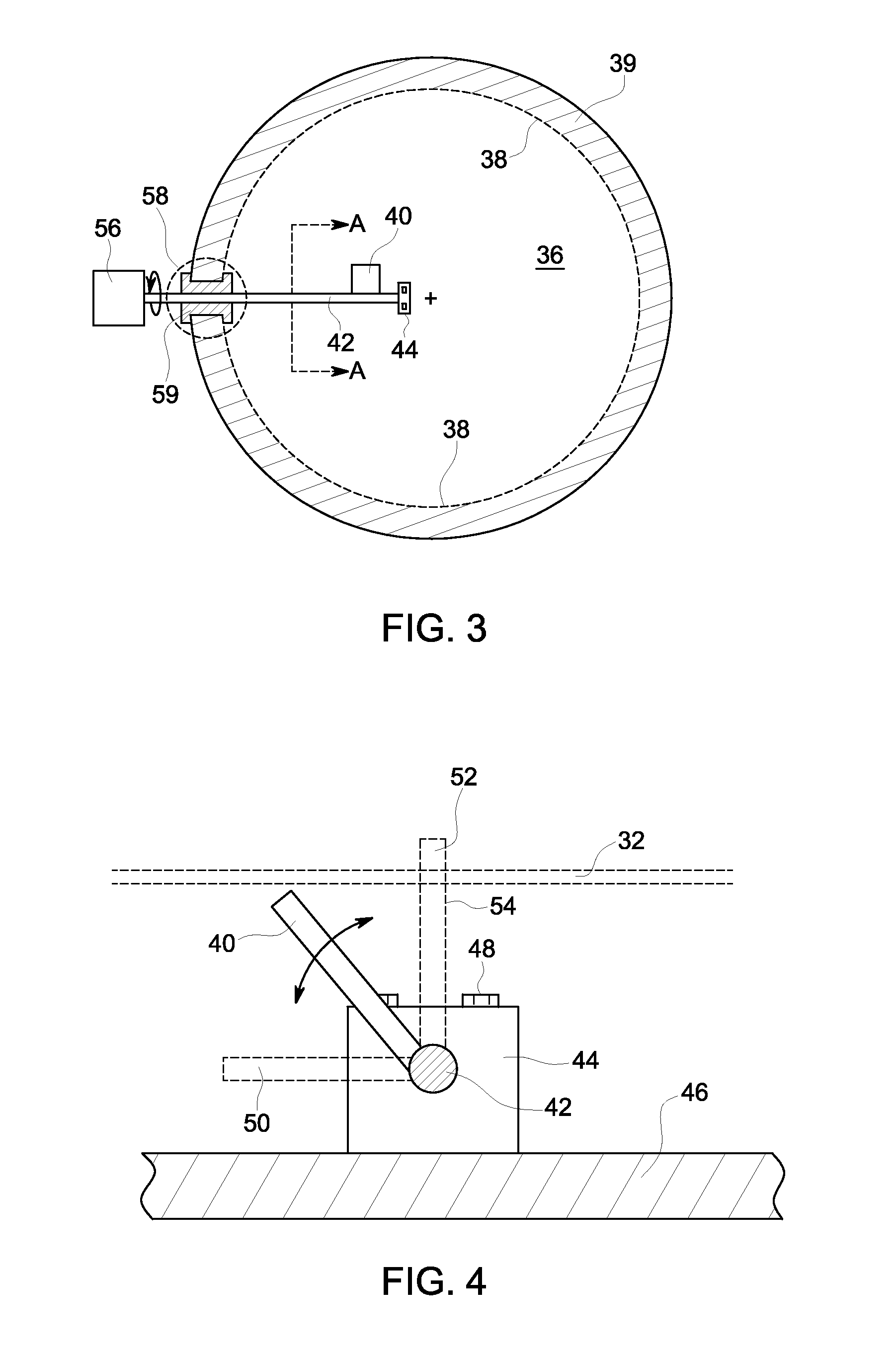
However, when utilizing feed-throughs 58 it is often difficult to prevent leaks and maintain an appropriate vacuum within the cyclotron chamber.
Additionally, it is typically not practical to place the stepper motor 56 (or other prior art devices for moving the probe 40 into position) inside the vacuum field 36 (rather than outside as illustrated in FIG. 3), due to electromagnetic interference that may be caused between the stepper motor 56 and the beam 32.

Method used


Image

  • Cyclotron actuator using a shape memory alloy
  • Cyclotron actuator using a shape memory alloy
  • Cyclotron actuator using a shape memory alloy

Examples


Embodiment Construction

[0026]The foregoing summary, as well as the following detailed description of certain embodiments of the present invention, will be better understood when read in conjunction with the appended drawings. It should be understood that the various embodiments are not limited to the arrangements and instrumentality shown in the drawings.

[0027]As used herein, an element or step recited in the singular and proceeded with the word “a” or “an” should be understood as not excluding plural of said elements or steps, unless such exclusion is explicitly stated. Furthermore, any references to a particular embodiment of the present invention are not intended to be interpreted as excluding the existence of additional embodiments that also incorporate the recited features. Moreover, unless explicitly stated to the contrary, embodiments “comprising” or “having” an element or a plurality of elements having a particular property may include additional such elements not having that property.

[0028]Variou...


PUM


Abstract

An actuator assembly for use within the vacuum field of a cyclotron, one embodiment of which comprises an interactor which is moveable between a first position and a second position, at least one support structure for supporting the interactor in the first and second positions, a shape memory alloy (SMA) element connected to the interactor and / or support structure and being adapted to exert a force on the interactor and / or support structure so as to urge the interactor from the first position to the second position, an electromagnetic activator operatively associated with the SMA element for causing the element to exert the force when the electromagnetic activator is selectably activated, and a return mechanism operatively connected to the interactor, the support structure and / or the SMA element so as to urge the interactor from the second position to the first position when the electromagnetic activator is deactivated.

Description

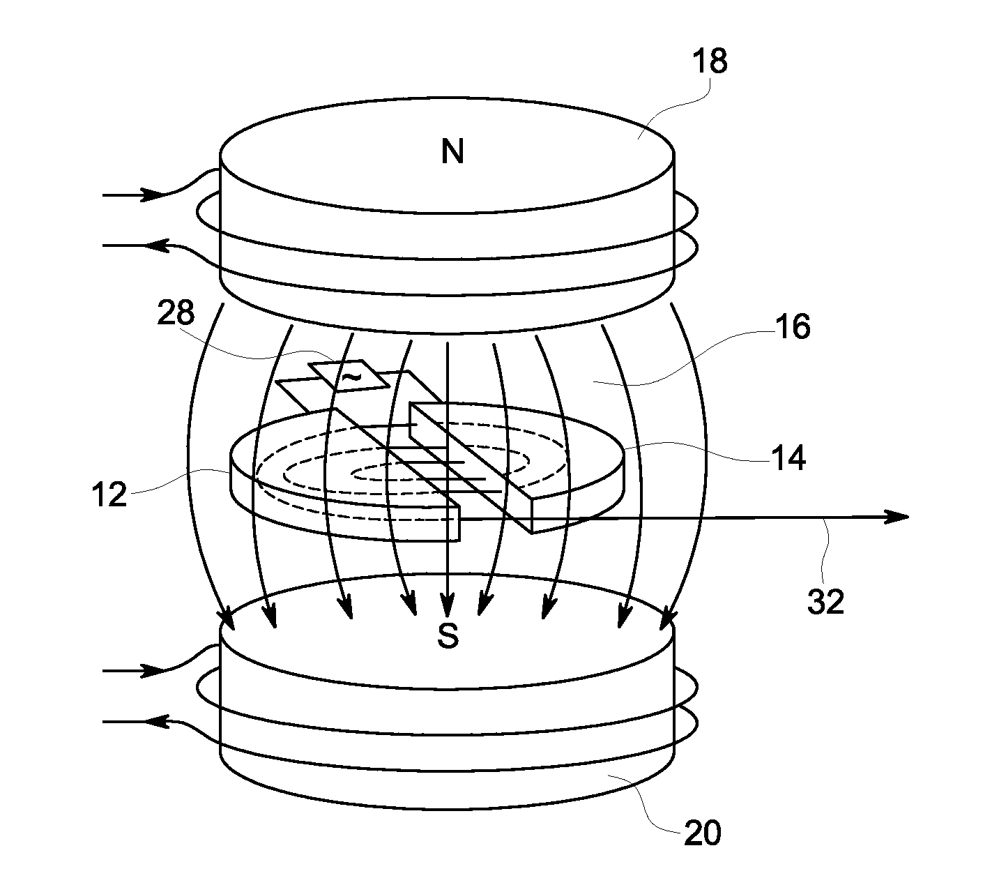
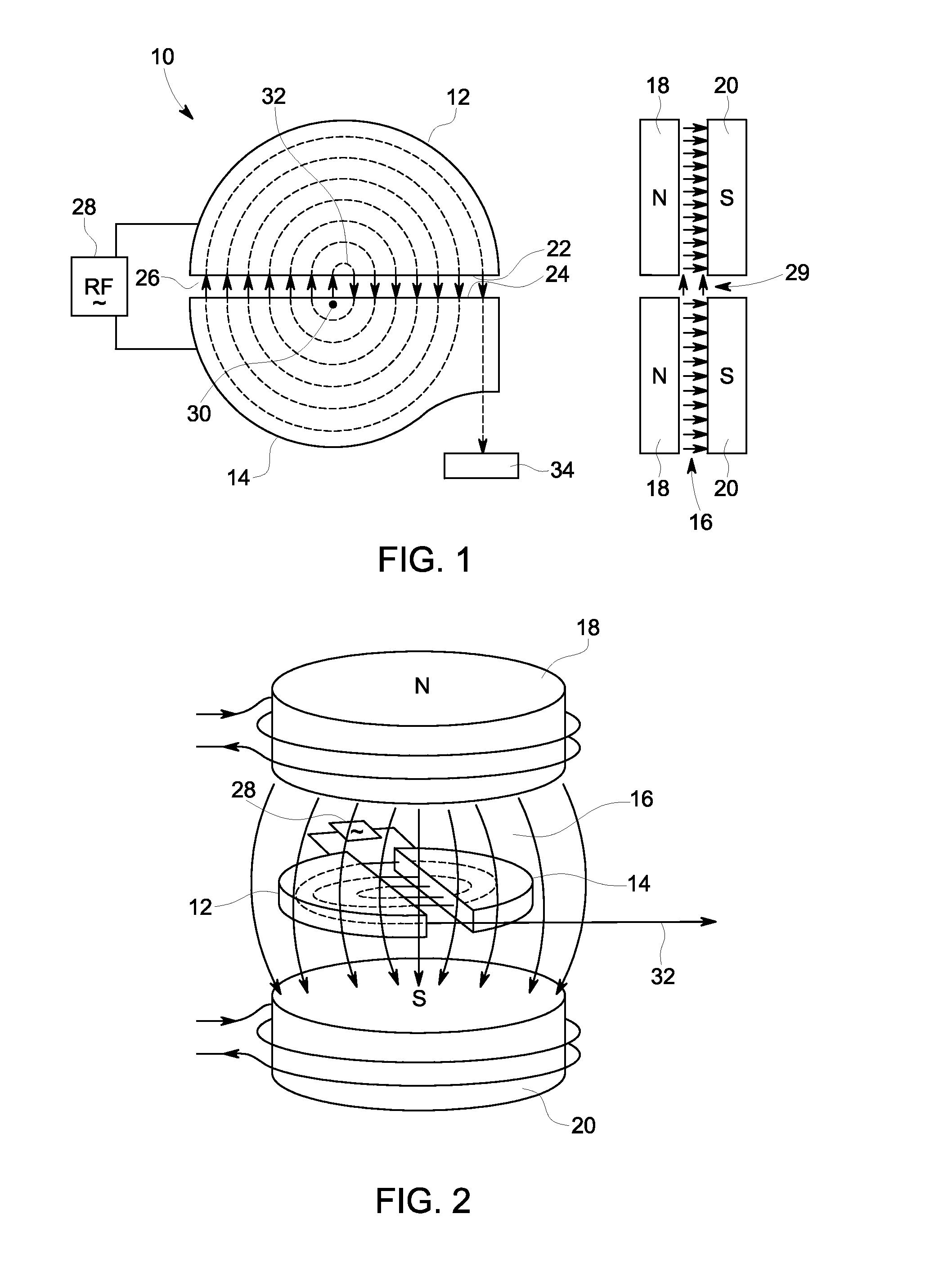
BACKGROUND OF THE INVENTION[0001]The present invention relates generally to actuators for use in cyclotrons, and more particularly to actuators for use in cyclotrons utilizing a Shape Memory Alloy.[0002]A cyclotron is a type of particle accelerator, which is used to accelerate charged particles (e.g., electrons, protons, alpha particles) up to high speed, thereby creating a beam or stream of charged particles. This beam may then be directed at a target made of a given material (e.g., H218O water or 18O2 gas) to produce particle-to-atom collisions in order to create different atoms (e.g., 18F2 gas), ions (e.g., 18F−) or other particles (e.g., alpha particles). These resulting atoms, ions or particles may then be put to various uses in research or medicine, such as for diagnostic imaging (e.g., positron emission tomography (PET), single photon emission computed tomography (SPECT), etc.) or radiation therapy (e.g., using alpha particles of electrons).[0003]FIGS. 1 and 2 illustrate a co...

Claims


Application Information

Patent Timeline
IPC IPC(8): H05H13/00
CPCH05H13/005
Inventor LARSSON, JOHAN
Owner GENERAL ELECTRIC CO
Learn More