Devices and methods for control of blood pressure

a technology of blood pressure and devices, applied in the field of implanted medical devices, can solve the problems of increasing and achieve the effects of reducing the activity of the baroreceptor in the portions of the vessel that are in contact with the device, reducing the contact between the device and the artery, and reducing the strain on the vessel wall

Active Publication Date: 2013-07-04
VASCULAR DYNAMICS
View PDF13 Cites 21 Cited by
  • Summary
  • Abstract
  • Description
  • Claims
  • Application Information

AI Technical Summary

Benefits of technology

[0010](1) A greater area of the artery pulsates in response to pressure changes than if the device were to maintain a greater degree of contact with the vessel wall. It is generally desirable to allow at least a portion of the vessel to pulsate freely. This is because pulsation of the vessel over the course of the cardiac cycle typically activates and maintains normal functioning of the baroreceptors. For some applications, baroreceptor activity in the portions of the vessel that are in contact with the device may be...

Problems solved by technology

As pressure increases, the stress exerted on the wall ...

Method used


Image

  • Devices and methods for control of blood pressure
  • Devices and methods for control of blood pressure
  • Devices and methods for control of blood pressure

Examples


Embodiment Construction

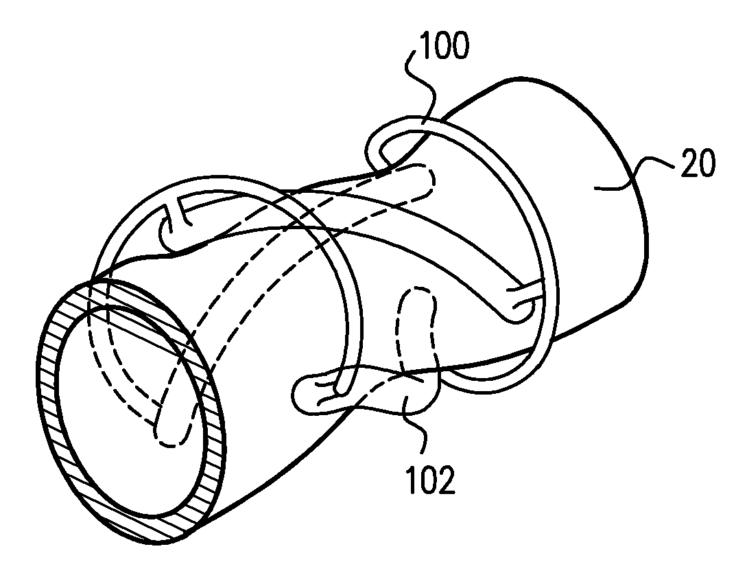
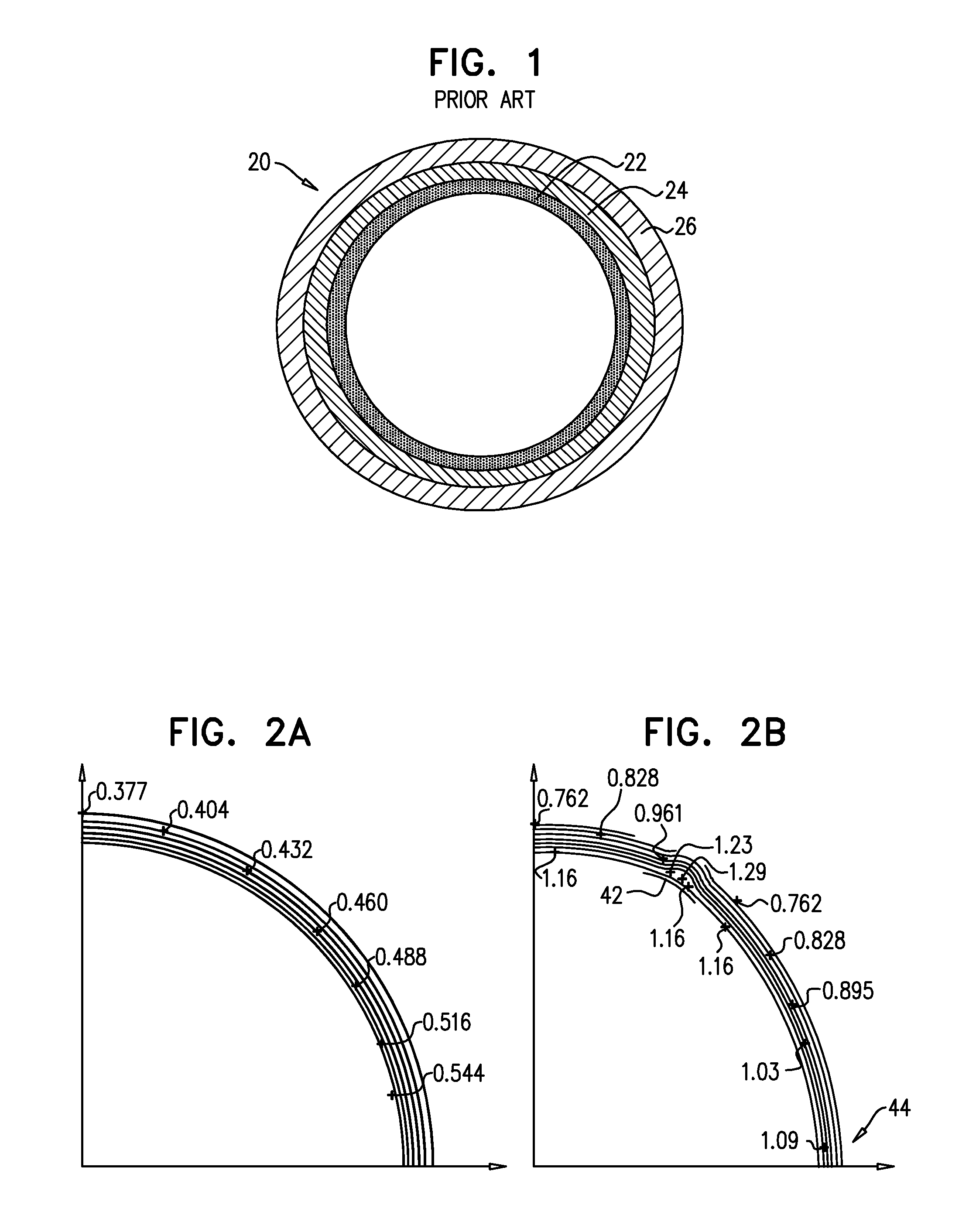
[0098]Reference is now made to FIG. 1, which is a cross-sectional illustration of an artery 20. The arterial wall includes three layers 22, 24, and 26, which are called, respectively, the intima, the media, and the adventitia. For some applications of the present invention, an intravascular device is placed inside an artery, baroreceptors being disposed at the interface between adventitia 26 and media 24 of the artery. The device causes the curvature of the arterial wall to flatten in some regions of the circumference of the arterial wall, thereby causing the baroreceptors to become stretched, while allowing the regions to pulsate over the course of the subject's cardiac cycle.

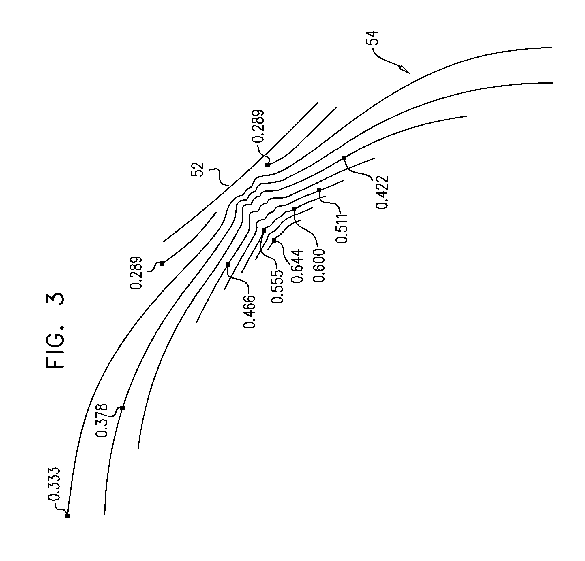
[0099]Reference is now made to FIGS. 2A and 2B, which are contour plots of the strain in the top right quarter of an arterial wall, in the absence of an intravascular device (FIG. 2A) and in the presence of an intravascular device (FIG. 2B), analyzed and / or provided in accordance with some applications of the ...


PUM


Abstract

Apparatus and methods are described including an implantable device having first and second longitudinal ends, the device having a length of less than 80 mm when the device is unconstrained. The device includes struts arranged such that, when the device is unconstrained, along a continuous portion of the device having a length that is at least 5 mm, a maximum inter-strut distance defined by any set of two adjacent struts is more than 1.5 times as great as a maximum inter-strut distance defined by any set of two adjacent struts within longitudinal portions of the device within 3 mm of the longitudinal ends of the device. Other applications are also described.

Description

CROSS-REFERENCES TO RELATED APPLICATIONS[0001]This application is a continuation-in-part of U.S. application Ser. No. 12 / 774,254 to Gross et al. (published as US 2011 / 0077729), filed May 5, 2010; and U.S. Ser. No. 13 / 030,384 to Gross et al. (published as US 2011 / 0178416), filed Feb. 18, 2011, which is a continuation-in-part of U.S. Ser. No. 12 / 774,254 to Gross et al., the entire contents of which are incorporated herein by reference.[0002]The present application is related to U.S. patent application Ser. No. 11 / 881,256 (US 2008 / 0033501), filed Jul. 25, 2007, entitled “Elliptical element for blood pressure reduction,” which is a continuation-in-part of PCT Application No. PCT / IL2006 / 000856 to Gross (WO 07 / 013,065), filed Jul. 25, 2006, entitled, “Electrical stimulation of blood vessels,” which claims the benefit of (a) U.S. Provisional Application 60 / 702,491, filed Jul. 25, 2005, entitled, “Electrical stimulation of blood vessels,” and (b) U.S. Provisional Application 60 / 721,728, fil...

Claims


Application Information

Patent Timeline
IPC IPC(8): A61F2/82
CPCA61F2/856A61F2/06A61F2/82A61F2250/0059A61B5/0215A61F2/915A61F2230/0021A61B5/0053A61F2230/0069A61F2/90
Inventor GROSS, YOSSIAVNERI, ITZIKWEISBERG, ORIESHKOL, MOSHEOREN, TALASSAF, YARONFELD, TANHUMELAZAR, MOSHE
Owner VASCULAR DYNAMICS
Why Eureka
Try Eureka