Method for Separating Entrained Catalyst and Catalyst Fines from Slurry Oil

a technology of catalyst fines and slurry oil, which is applied in the direction of filtration separation, separation processes, moving filter elements, etc., to achieve the effects of reducing the demand for fresh catalysts, prolonging the run-length of fluid catalytic cracking (fcc) process, and high loss ra

Inactive Publication Date: 2013-07-11
CAMERSON INT CORP
View PDF4 Cites 5 Cited by
  • Summary
  • Abstract
  • Description
  • Claims
  • Application Information

AI Technical Summary

Benefits of technology

[0014]Objects of this invention are to extend fluid catalytic cracking (FCC) process run-length; recover a significant percentage of the fines and almost all of the catalyst lost to slurry oil; reduce fresh catalyst demand when reactor cyclones experience high loss rates; provide a low fines content in the separated slurry oil ahead of downstream heat exchangers, steam generators, control valves, pumps, and process lines; and reduce or eliminate the need for fines settling and cleanout in storage tanks.

Problems solved by technology

Of all the refinery processes, the FCC process has one of the highest operating costs and is one of the most difficult to operate reliably for extended periods of time.
To date no long term, cost effective and operationally viable solutions have been found.
This is particularly true when it comes to dealing with FCC fractionator slurry oil and the operational problems created when it becomes contaminated.
This contamination occurs naturally at very low levels with undamaged and properly designed riser termination and primary and secondary cyclones in the FCC reactor.
During an upset in the reactor, or as the FCC reactor is reaching the end of its planned run length, loss rates of catalyst and fines, along with coke fine generation, can increase to much higher levels, thereby affecting operational control of the FCC process.
Poorly operating reactor cyclones can result in elevated levels of fresh or equilibrium catalyst loss to slurry oil in the range of 3 to 5 tons per day over the typical 1 to 3 tons per day normally seen.
Catalyst and fines contamination, especially when it occurs for extended periods of time, causes one or more of the following undesirable effects:1. Increased metallurgical loss rates due to erosion in the slurry oil loop affecting heat exchangers, steam generators, control valves, pumps, and process lines.2. Increased fouling and plugging of slurry oil loop fractionators, heat exchangers and steam generators, as well as high pressure drops.3. Increased fouling of slurry oil decant and storage tank bottoms while settling catalyst from slurry oil to meter intermediate or product ash content specifications.4. Increased operational cost to repair the damaged or fouled equipment.5. Increased operational costs to clean and dispose of Resource Conservation and Recovery Act (RCRA) hazardous oil wet solids in the bottom of slurry oil storage tanks.6. Increased operating difficulty in meeting optimum unit performance.
Next to the cost of the catalyst itself, dealing with the above issues can become the second highest operating cost in the FCC process.
As the severity of contamination increases, it becomes a major limiting factor to meeting run-length expectations while maintaining optimum product conversion and yield.
Currently there are no technologies that can recover catalyst, catalyst fines and coke particles from a FCC fractionator slurry oil loop because of temperature, pressure and size limitations.
Several manufacturers have sold a limited number of these filtration units over the last 10 to 15 years, but few if any of these units are operational today.
Although the units meet expectations in terms of removal efficiency, the capital and operating costs are prohibitively high and operational control proves difficult and complex.
Additionally, inventorying, cleaning and replacing filters is labor-intensive and complicated, redundant filter housings are required, and the filters have to be backwashed frequently.

Method used


Image

  • Method for Separating Entrained Catalyst and Catalyst Fines from Slurry Oil
  • Method for Separating Entrained Catalyst and Catalyst Fines from Slurry Oil
  • Method for Separating Entrained Catalyst and Catalyst Fines from Slurry Oil

Examples


Embodiment Construction

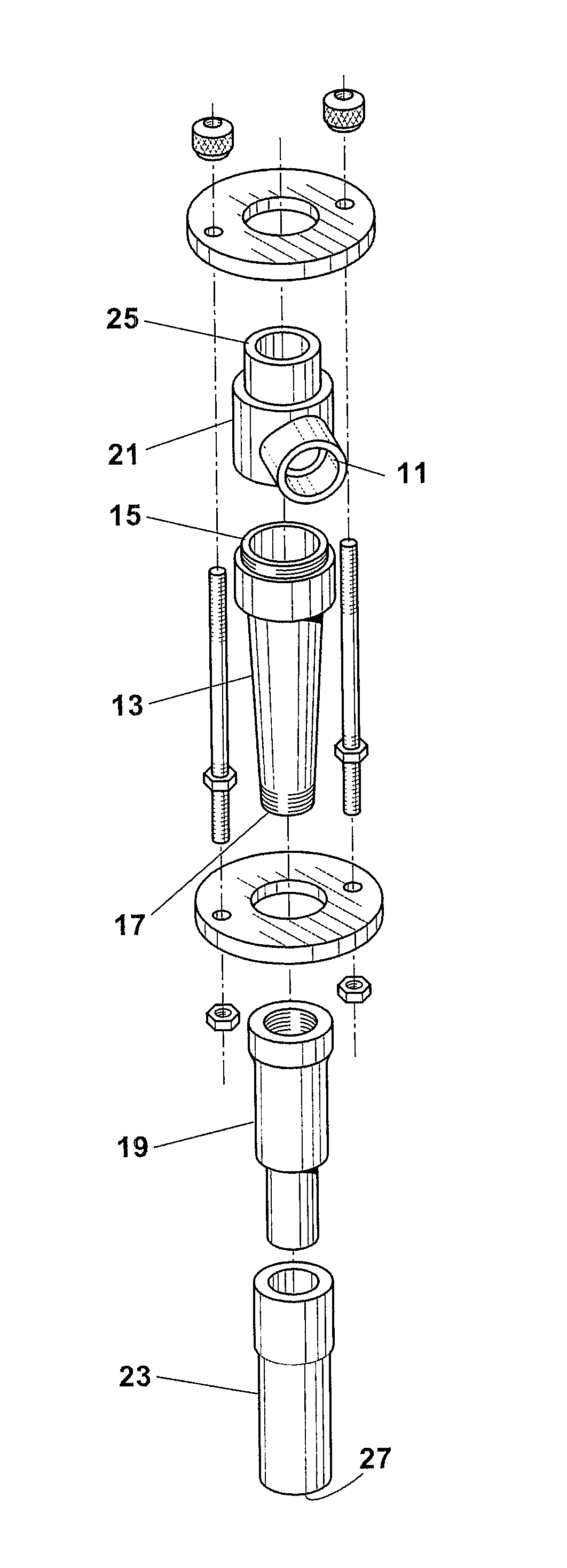
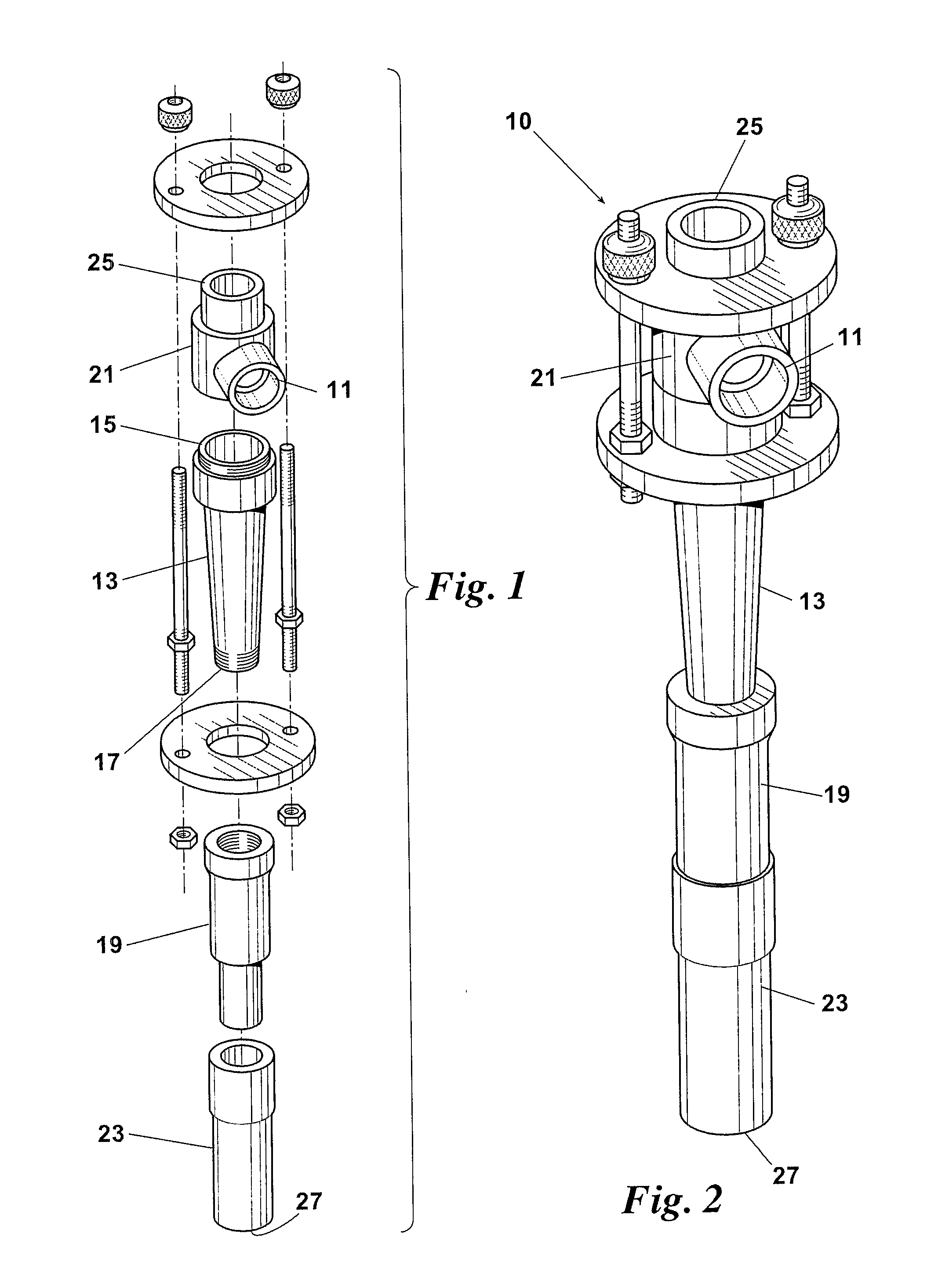
[0022]Preferred embodiments of a method for removing entrained catalyst, catalyst fines and coke particulates from a slurry oil stream will now be described in reference to the drawings. Elements shown by the drawings are identified by the following numbers:

[0023]FIGS. 1 & 2 illustrate a hydrocyclone vessel 10 well-suited for use in this method, namely, a MOZLEY™ hydrocyclone (CAMERON Process Systems, Houston, Tex.). Hydrocyclone 10 has an inlet 11 to a vortex finder cap 21 located at the upper or overflow end 15 of the body 13. The inlet flow entering inlet 11 is directed tangentially into the cap 21. Vortex finder cap 21 is designed to create spin and centrifugal force in the incoming oil slurry stream and provide for a predetermined d50 cut point. The entrained catalyst, catalyst fines and coke particulates move outward toward the internal walls of the body 13 where they mass and spin down the wall toward underflow end 17 and into spigot 19. Spigot 19 is selected to allow precise...


PUM

PropertyMeasurementUnit
particle sizeaaaaaaaaaa
temperatureaaaaaaaaaa

Abstract

A method for removing catalyst, catalyst fines, and coke particulates from a slurry oil stream includes the steps of routing a first slurry oil stream from a first slurry oil source to at least one hydrocyclone, increasing at least one of a temperature and a pressure of the first slurry oil stream prior to it entering the at least one hydrocyclone; passing the first slurry oil stream through the at least one hydrocyclone; and routing a second slurry oil stream exiting an overflow end of the at least one hydrocyclone to a second slurry oil source. The first and second slurry oil sources may be one or more of the following: a main column of a fluid catalytic cracking fractionator, a steam generator, a heat exchanger, a decant slurry oil storage, and a slurry oil storage tank.

Description

BACKGROUND OF THE INVENTION[0001]The present invention relates generally to systems, apparatuses and processes associated with the fluid catalytic cracking (FCC) process used in petroleum refineries. More particularly, the invention relates to systems, apparatuses and processes for removing catalyst, catalyst fines and coke particulates typically found in the bottom stream or slurry oil of FCC reactors.[0002]The FCC process is designed to thermo-catalytically upgrade the yield and quality of higher boiling point, distillate, intermediate products provided by the crude atmospheric and vacuum fractionators located upstream in the crude oil refining process. Of all the refinery processes, the FCC process has one of the highest operating costs and is one of the most difficult to operate reliably for extended periods of time. This process is also the primary source of high quality olefans and isobutene for alkylation into a low sulfur and high octane gasoline stream. Therefore, the FCC p...

Claims


Application Information

Patent Timeline
Patent Type & Authority Applications(United States)
IPC IPC(8): C10G31/10B01D21/26
CPCB01D21/267B01J8/0055C10G11/18C10G2300/70C10G11/187C10G2300/4081C10G11/182C10G31/10
Inventor HYPES, RONALD D.
Owner CAMERSON INT CORP
Why Eureka
Try Eureka