Multi-component mixing system having a rotatable container and container therefor

a multi-component mixing and container technology, applied in the field of containers, can solve the problems of high friction loss, inability to vary the preparation time of users, and high stress on the shaft and seal, so as to reduce the size of the device, reduce the distance between the container and the mixing nozzle, and simplify the replacement of individual containers

Active Publication Date: 2013-07-18
HERAEUS KULZER
View PDF18 Cites 16 Cited by
  • Summary
  • Abstract
  • Description
  • Claims
  • Application Information

AI Technical Summary

Benefits of technology

[0049]In this way, because the drive occurs via the outer walls of the container body, in this container according to the invention, the drive can sit next to the container, and thus allow a simple replacement of individual containers. Here, the other containers can remain in the container system. At the same the openings, which are also feed channels to the mixing nozzles, can have short constructions. If the drive is realized, however, by a head plate on the spindle, the distance between the container and mixing nozzle increases also. This is disadvantageous both on account of loss of material and also loss of force due to the longer throughflow channels. By reducing to a total of three necessary components consisting of two base components from whose mixture ratio the consistency is regulated, and the activator component, whose dosing quantity controls the processing time, the entire feeding mechanism can be driven by a single motor. The respective dosing ratios are here regulated by gears, which would have the advantage of reducing the device size.
[0050]Advantageously, however, instead of using a universal activator component, the preselected processing time is controlled by the ratio of two different components. These two components can be two activator components having different reactivity values. Likewise, it has also proven effective to use a combination of a catalyst component and a decelerating component (retarder, inhibitor), which can be used combined with each other according to the preselected processing time. If a combination of a catalyst / decelerator is used, the total portion of these components relative to the portion of base components can be held constant, which is advantageous for controlling the preselected consistency.

Problems solved by technology

Because the mixing ratios of the base paste and catalyst paste are fixed, the devices have a common conveying feed for both components, so that the preparation time cannot be varied by the user, in which, for example, more or less catalyst paste is added relative to the base paste.
One problem of these rigid connections is that under pressure strong stresses occur on the shafts and seals due to deformation of multiple parts of the entire system.
As a result, higher friction losses occur, which significantly increase the drive energy to be applied for mixing or feeding or lead to leaks at sealing surfaces.
Due to the large forces occurring, the parts must have a very stable construction, which increases the material consumption, the weight, and the costs.
On the other hand, the containers are susceptible to failure or can even be completely destroyed during operation.
Another disadvantage is that the replacement of the containers is time intensive due to the construction, since the drive must be connected to the shaft in a force-fit manner.
Finally, it cannot be seen for the produced mixture whether the correct mixing ratio was used.

Method used


Image

  • Multi-component mixing system having a rotatable container and container therefor
  • Multi-component mixing system having a rotatable container and container therefor
  • Multi-component mixing system having a rotatable container and container therefor

Examples


Embodiment Construction

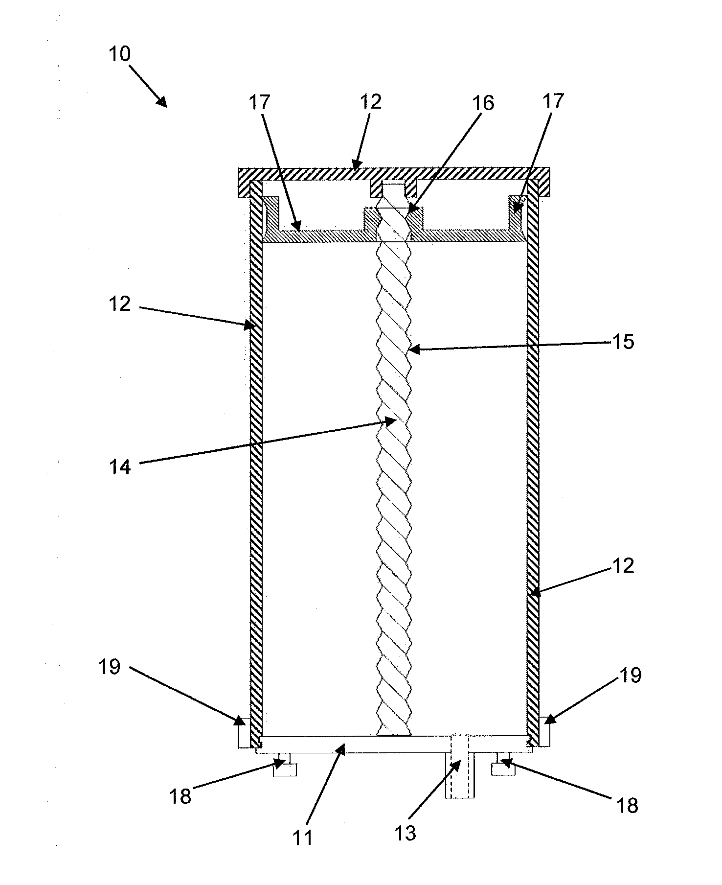
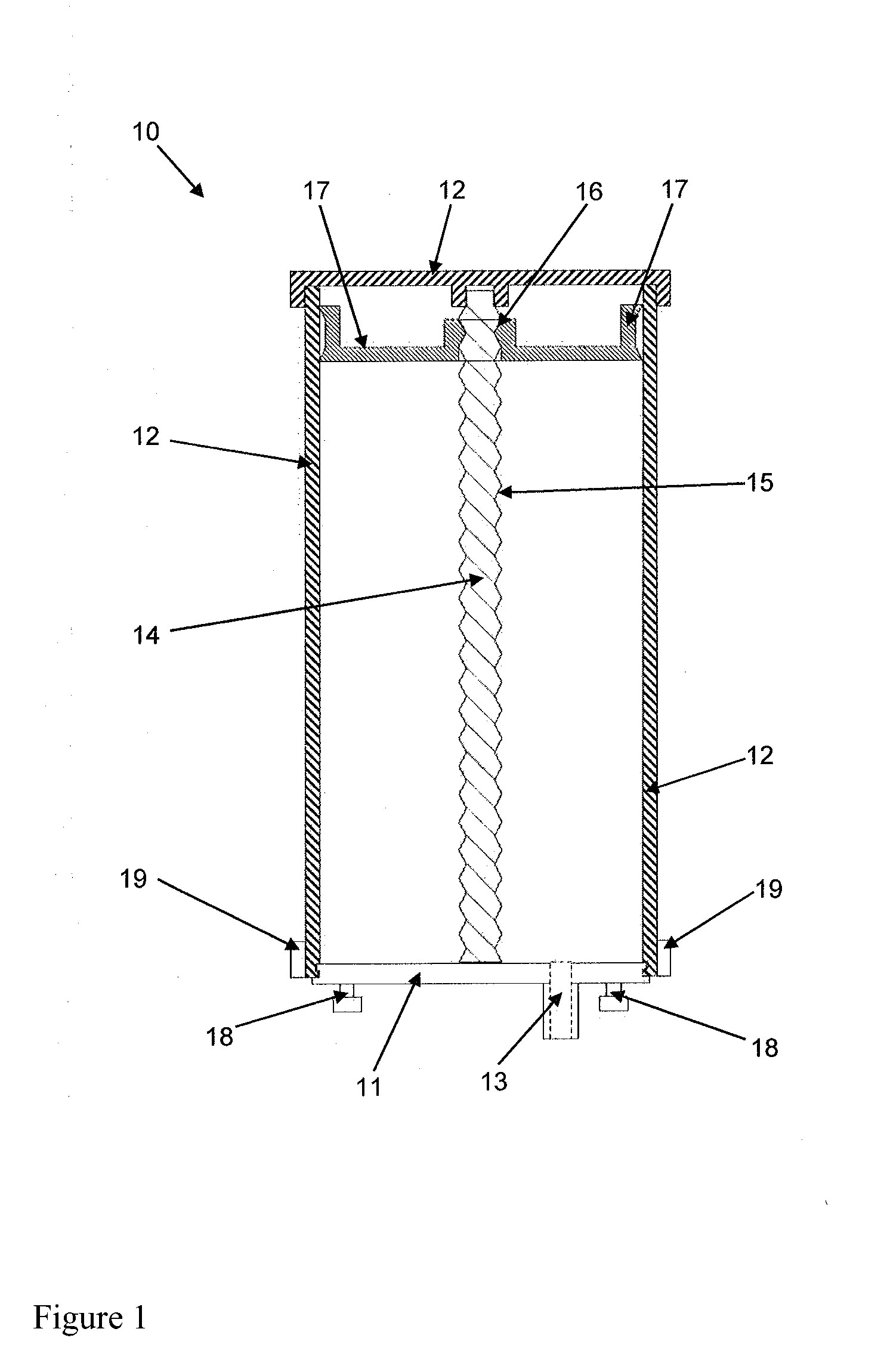
[0059]FIG. 1 shows a schematic longitudinal section view along the longitudinal axis of a container 10 according to an embodiment of the invention. This container has a cover 11 that can be removed, in order to fill the container 10 with molding material. The container 10 comprises, in addition to the cover 11, a container body 12 that, together with the cover 11, seals the container 10 against the outside. The container body 12 is mounted relative to the cover 11 so that it can rotate about an axis running perpendicular through the cover 11. The cover 11 includes an outlet opening 13. On the side opposite the cover 11 the container 10 is closed.

[0060]A spindle 14, which acts as a drive shaft, runs centrally through the container 10, which has a tubular cross section. The spindle 14 is connected rigidly to the cover 11. The spindle 14 has a thread in the shape of an external thread 15 that interacts with a counter thread in the form of an internal thread 16 of a piston 17. The pisto...


PUM

PropertyMeasurementUnit
volumeaaaaaaaaaa
rotational speedsaaaaaaaaaa
massaaaaaaaaaa

Abstract

A container (10, 30, 50) is provided for single- or multi-component molding materials. The container has a container body (12, 32, 52) having a constant outer contour in a longitudinal extent of the container (10, 30, 50), a piston (17, 37) movable in the longitudinal direction, and a cover (11, 31) having an outlet opening (13, 33, 53). A volume for a molding material is defined between the piston (17, 37) and the cover (11, 31), the volume being variable in the direction of the longitudinal extent of the container (10, 30, 50). The container distinguishes itself in that the container body (12, 32, 52) is rotatable relative to the outlet opening (13, 33, 53), and the piston (17, 37) thereby pushes out the content of the container (10, 30, 50).

Description

CROSS-REFERENCE TO RELATED APPLICATIONS[0001]This application is a Section 371 of International Application No. PCT / EP2011 / 004590, filed Sep. 13, 2011, which was published in the German language on Mar. 29, 2012, under International Publication No. WO 2012 / 038038 A1 and the disclosure of which is incorporated herein by reference.BACKGROUND OF THE INVENTION[0002]The invention relates to a container for single-component or multi-component molding materials, comprising a container body having a constant outer contour in a longitudinal extent of the container, a piston movable in the longitudinal direction, and a cover having an outlet opening, wherein a volume provided for a molding material is defined between the piston and the cover, the volume being variable in the direction of the longitudinal extent of the container. The invention also relates to a container system for multi-component molding materials having at least two such containers, a method for applying a mass from such a c...

Claims


Application Information

Patent Timeline
Patent Type & Authority Applications(United States)
IPC IPC(8): G01F11/00B29B7/80B01F29/87
CPCB01F13/1055B01F15/0237B29B7/80B65D83/0027A61C9/0026B65D83/0011B01F33/84B01F35/7174
Inventor NEHREN, KLAUS-DIETERGRUNDLER, ANDREASFRIESE, UDOBOTZUM, SUSANNEMEIER-STAUDE, MANUELJASPER, GUENTERLANZENDORF-LINKWEILER, UWEHENNEN, HEIKEMEMMER, ALFFRECKMANN, MICHAEL
Owner HERAEUS KULZER
Why Eureka
Try Eureka